Loading the model
This device cannot show the 3D model. You can read the guide steps below as text.
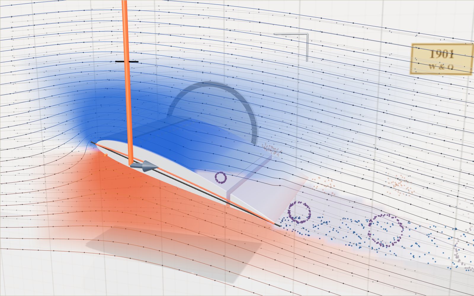
1 / 11 A wing in a wind tunnel This is a slice of a light-aircraft wing with air blowing past it from the left. The dots ride along the streamlines, and the colours on the skin show the pressure.
Drag to turn. Scroll or pinch to zoom.
Guide Parts Controls
01 A wing in a wind tunnel This is a slice of a light-aircraft wing with air blowing past it from the left. The dots ride along the streamlines, and the colours on the skin show the pressure.
02 The shape comes from a formula NACA 2412 means 2% camber, placed 40% back from the nose, and 12% thickness. The red line is the camber line and the black one is the chord.
03 Where the air splits At 6° the air meets the wing slightly under the nose, at the orange line. Some of the air that splits off there has to run forward around the nose and then back over the top.
04 Not the same time The orange lines join dots that set off together. Watch them pass the wing. The upper ones arrive at the trailing edge well before the lower ones, and they never catch up.
05 Lift equals weight At 220 km/h the wing needs only 1.5° to hold up 10.9 kN. The readout works out L = ½ρv²SC_L with the numbers on screen.
06 Stall Past about 17° the flow leaves the upper surface. Lift drops instead of growing, and the drag arrow gets long.
07 Flaps for landing With 30° of flap the same weight is carried at 100 km/h. The flap bends the camber line down and shifts the whole lift curve up.
08 Inside the wing The skin is see-through here. Two spars and a row of ribs give the thin metal its shape and carry the load to the fuselage.
09 Slat and spoiler With the slat out the wing still flies at 19°, where the bare wing has stalled: the stall comes about 5° later. Raise the spoiler instead and the flow breaks up behind it, so lift drops.
10 The vortex at the tip Air below the wing spills round the free tip towards the low pressure on top and rolls up into a vortex. The harder the wing lifts, the faster it spins.
11 Takeoff in thin air On the runway lift grows with the square of the speed until it matches the weight. At Everest height the air is less than half as dense, so the same plane needs a faster and much longer run.
Wing skin NACA 2412 section, 12% thick. Blue means pressure below the air around it, red means above. Flap Hinged at 75% of the chord. Goes down 10°, 20° or 30°, like the steps on a Cessna 172. Main spar The beam that carries the lift to the fuselage. It sits near the thickest part of the section. Rear spar A lighter beam that closes the wing box and holds the flap hinges. Ribs They hold the skin to the airfoil shape. The holes save weight. Chord line The straight line from nose to tail. The angle of attack is measured from it. Camber line Halfway between top and bottom. Here it bulges 2% of the chord at 40% back. Stagnation line Where the air comes to rest on the nose and splits. It slides under the nose as the angle grows. Streamlines Computed with a panel method each time you change the angle or the flap. Lift and drag Red arrow is lift, grey is drag. The black tick marks the weight of a 1,111 kg aircraft. Slat It slides forward and down from the nose and opens a slot. Here it raises the highest lift coefficient by 0.45, so the stall comes about 5° later (model values). Spoiler A plate that rises from the top of the wing. It breaks up the flow behind it, cuts lift and adds drag. Tip vortex Air below the wing spills round the free tip to the low pressure on top and rolls up. Drawn by rule: it grows with the lift coefficient.