Loading the model
This device cannot show the 3D model. You can read the guide steps below as text.
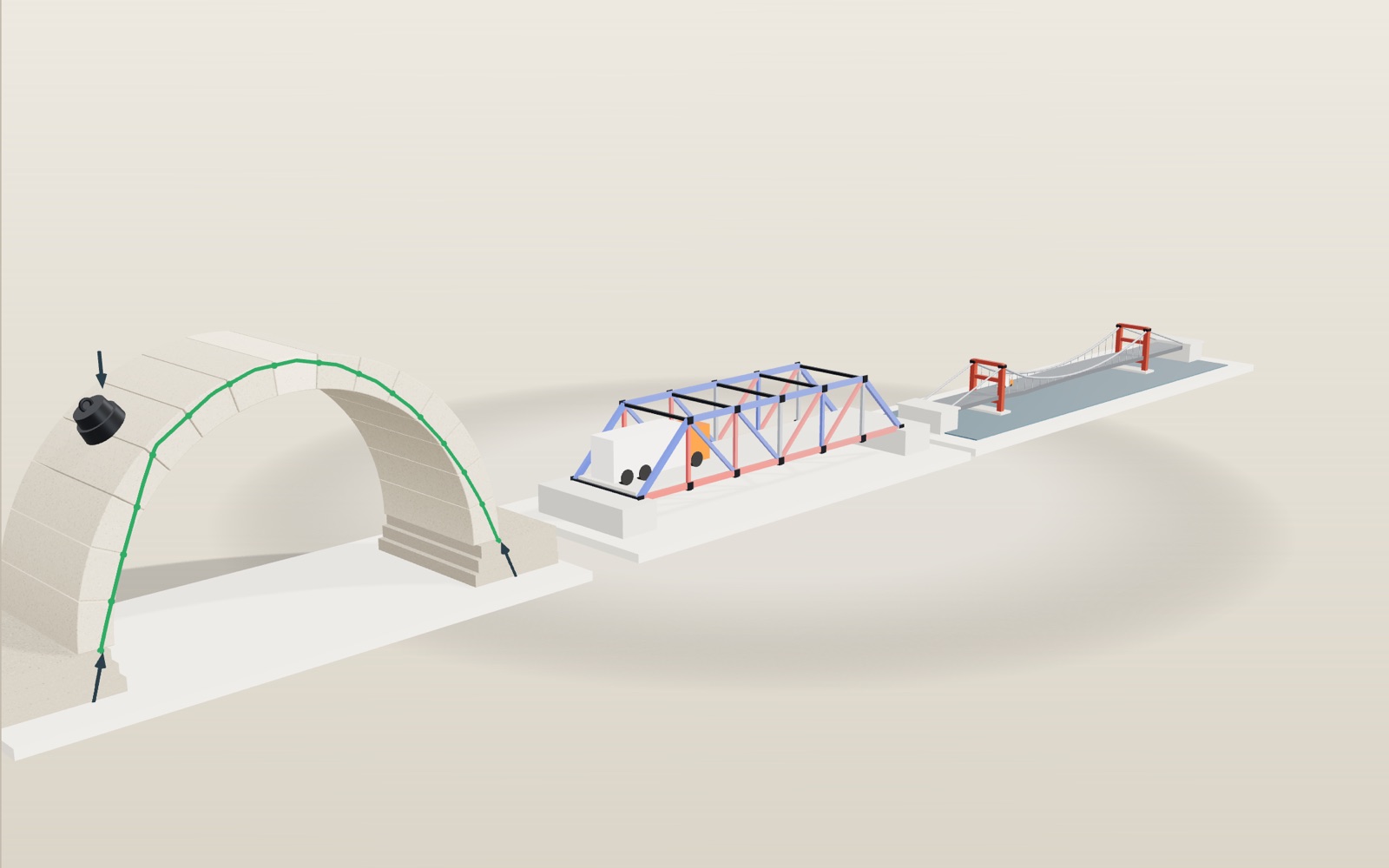
1 / 11 A load crosses a stone arch One stone arch fills the stage while a cast-iron weight rolls over it. The green line is the path of the push through the stones, and the dots running down it show the force travelling to the abutments. Drag the weight yourself to move it.
Drag to turn. Scroll or pinch to zoom.
Guide Parts Controls
01 A load crosses a stone arch One stone arch fills the stage while a cast-iron weight rolls over it. The green line is the path of the push through the stones, and the dots running down it show the force travelling to the abutments. Drag the weight yourself to move it.
02 Stones on a timber frame Ten of the 15 stones are laid. Until the ring is closed nothing holds them except the timber centring underneath. Turn the centring off here and the stones fall.
03 The keystone closes the ring With the keystone in, the centring can come out. The green line is a thrust line: the path of the compressive force from stone to stone. It stays inside the ring, so the arch stands.
04 Too much load in one place 180 kN at a quarter of the span pushes the thrust line out of the ring. Red dots mark joints where no line can stay inside, which is where the stones would start to hinge open.
05 Pull a stone out yourself Tap any stone in the ring. It slides out, and with nothing under it the whole ring falls, the keystone included. Press the button on the stage to put the stones back.
06 A truck in the middle of the truss Each of the two trusses takes 100 kN. The top chord carries 150 kN of compression and the bottom chord 100 kN of tension, worked out joint by joint.
07 Move the truck to one third Now the diagonal U2L3 changes from 71 kN of tension to 47 kN of compression. Moving loads are the reason truss members have to be checked for both.
08 Why the cable is a parabola With only the deck hanging from it, the cable carries equal loads at equal spacing. Its shape then follows the bending moment of a uniformly loaded beam, which is a parabola.
09 Towers, anchorages and a truck A 300 kN truck at a quarter of the span pulls the cable into a kink, drawn ten times larger here. The pull goes over the towers and down the back spans into the anchorages.
10 Real bridges at their own proportions The Golden Gate Bridge has a 1,280 m main span and towers 227 m above the water, so the span is about 5.6 times the tower height. Pick the other bridges below the stage and compare.
11 Three bridges side by side The three models stand in a row again, each drawn to its own scale. The same load crosses all three: the arch pushes, the truss splits the load into push and pull, and the cable only pulls.
Voussoirs 15 wedge-shaped stones, each covering 12° of the ring. The ring is 0.6 m thick, 3 m wide and 4 m in radius at its centreline, and one stone weighs 35 kN. Keystone The stone at the crown, laid last. In the model it has the same shape and weight as the others; it matters because it is the one that closes the ring. Centring A temporary timber frame that holds the stones while the ring is incomplete. Knocking out the wedges on top of the posts lowers it a few centimetres so the arch can take its own weight. Abutments The arch pushes outward as well as down. Under its own weight each abutment takes 104 kN sideways and 266 kN downward. Top and bottom chords With the truck in the middle the top chord is squeezed (blue) and the bottom chord is pulled (red). Together they act like the top and bottom of a beam 5 m deep. Verticals In a Pratt truss the verticals are usually in compression. The ones nearest the ends carry nothing unless the load stands right on their joint. Diagonals They slope down toward the middle and carry the shear. With the truck in the middle they are all in tension, but a diagonal on the far side of the truck can flip to compression. Deck The road deck of the suspension bridge. The model treats it as a chain of short spans between hangers, so it has no stiffness of its own. Main cables Two cables over a 160 m main span with 16 m of sag. Under the deck's weight each one pulls sideways with 8,000 kN. Hangers Vertical rods every 8 m. Each one hands 320 kN of deck weight up to the cable, the same amount at every hanger. Towers They hold the cables up at the saddles. The cable pulls the same amount sideways on both sides, so the towers mostly carry a vertical load. Anchorages Concrete blocks at the ends of the back spans. Each cable pulls on its anchorage with 8,400 kN, about 2,560 kN of it upward.