Loading the model
This device cannot show the 3D model. You can read the guide steps below as text.
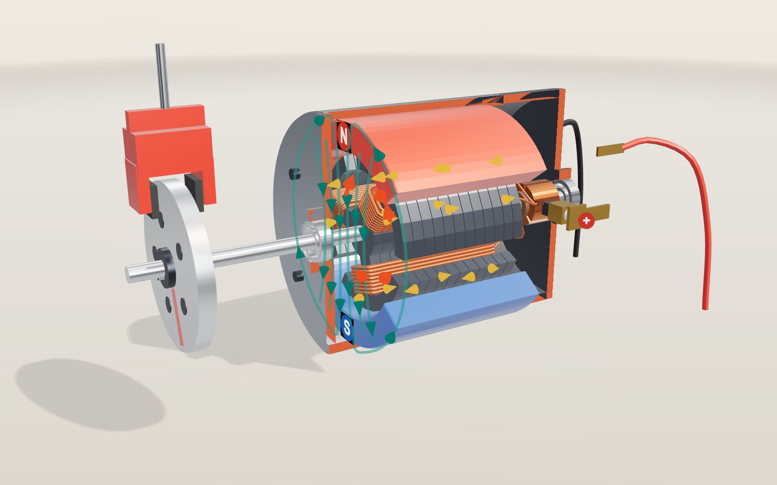
1 / 17 A small DC motor, cut open The near half of the case and the end cap has been cut away, and the red edges show the cut. Inside, a three-pole armature turns between two magnets. This is one of eight motors here: pick others from the Motor slider or the list under the controls.
Drag to turn. Scroll or pinch to zoom.
Guide Parts Controls
01 A small DC motor, cut open The near half of the case and the end cap has been cut away, and the red edges show the cut. Inside, a three-pole armature turns between two magnets. This is one of eight motors here: pick others from the Motor slider or the list under the controls.
02 Two magnets make the field The red magnet faces the rotor with its north pole and the blue one with its south. The green lines show the field crossing the gap and the iron core, then returning through the steel case.
03 The push on each wire: F = BIL A wire carrying current across a magnetic field is pushed sideways with a force F = B·I·L. The red arrows show that push on both sides of each coil. The hand shows Fleming's left-hand rule: first finger along the field, second finger along the current, and the thumb gives the force.
04 The commutator switches the current Without a switch the armature would stop where the pulls balance. The copper segments turn with the shaft, so the brushes reach a new pair every 60° and each coil's current reverses every half turn. The model slows down at each switch so you can see the spark at the brush.
05 A heavier load slows it down A turning coil is also a generator, and its back EMF k·ω pushes against the supply. When the brake grips harder the motor slows, the back EMF falls and more current flows, until the torque k·I matches the load. At 12 V and 80 mN·m it runs at 1,910 rpm and draws 4 A.
06 Turned backwards, it charges With Regenerative braking on, the load drives the shaft instead of holding it back. The motor turns faster than its supply would push it, the back EMF wins, and the current flows back into the battery: at 12 V and 40 mN·m, 7,639 rpm and 24 W of charging.
07 Brushless: a chip does the switching This drone motor turns its magnets outside the coils. There are no brushes; three hall sensors at the back feel the magnets go past, and the driver switches two of the three phases at a time. Red coils are north poles at that moment, blue are south.
08 Three phases make a turning field Each stator slot carries one of three alternating currents, each a third of a cycle behind the last. Added up they make a field that turns at a steady speed. With two poles and 50 Hz the field goes around 3,000 times a minute; the purple arrows show it.
09 The cage always lags a little The rotor is a cage of aluminium bars. Only when it turns slower than the field does the field sweep past the bars and induce currents in them, which is why an induction motor slips behind. At 4 poles and its rated 26.5 N·m this one runs at 1,451 rpm against a field of 1,500.
10 Frequency sets the speed An inverter can change the frequency. The field speed is 120·f / p: at 30 Hz with 4 poles it is 900 rpm and the rotor runs at 849 rpm under the same load. Pumps and fans save power this way instead of throttling the flow.
11 Magnets in the rotor: the EV motor An electric car's motor has magnets buried in the rotor in V shapes, so it turns exactly with the field. At 200 Hz and 8 poles that is 3,000 rpm; the load only changes the angle by which the rotor lags the field. Here it gives 100 N·m and 31.4 kW.
12 Gears, wheels and regenerative braking The reduction gear turns 6,000 rpm into the speed of the wheels, about 88 km/h with this gear and wheel. When the driver lifts off, the inverter makes the motor a generator: the wheels drive it and the battery takes the current.
13 A stepper moves in steps The 50 teeth on the rotor and two phases in the stator give 200 full steps per turn, 1.8° each. The driver changes the currents pulse by pulse; at 200 steps per second the shaft turns once a second. Between pulses it holds still.
14 A servo goes to an angle Inside the case: a small DC motor, a gear train, a potentiometer on the output shaft and a control board. A 2.0 ms pulse asks for +90°; the board drives the motor until the potentiometer agrees, then holds.
15 Unrolled flat: the linear motor Cut a motor open and lay it flat, and the turning field becomes a field that travels. The stator runs along the guideway and the magnets ride on the vehicle. Its speed is 2·τ·f: 100 Hz with the model's 0.25 m pole pitch gives 180 km/h.
16 Where it began: Faraday, 1821 A wire hangs from a pivot with its end in a bath of mercury, around a magnet standing upright. When the battery drives a current down the wire, the magnet's field pushes it sideways and it circles the pole. Turn the magnet over and it circles the other way.
17 Taken apart The housing slides back, the rotor with its magnets and shaft comes out of the front, and the inverter lifts off the top. The stator with its windings stays in place: in every motor here, that is the part that does not turn.
Housing The outer shell. On the DC motor it is a steel can that also carries the field around the outside. Magnet (N) Faces the rotor with its north pole. Small motors usually use ceramic ferrite. Magnet (S) Faces the rotor with its south pole. The field crosses the rotor from N to S. Armature core A stack of 12 thin steel plates with three arms. Thin plates keep eddy currents small. Armature coils Enamelled copper wire wound around each arm. The three coils are joined in a ring. Commutator Three copper segments with 8° gaps, turning with the shaft. Each segment joins two coils. Brushes Carbon blocks pressed onto the commutator by springs. The + brush is on the near side. Shaft Steel shaft carrying the rotor and passing the torque to the load. Bearings One at each end. They keep the rotor centred in the narrow air gap. End cap Plastic back cover of the DC motor, holding the brushes and the two terminals. Load What the motor drives: a disc with a brake on the DC motor, a coupling on the induction motor, a pointer on the stepper. Brake Pads squeeze the disc to make a load torque. Set it with the Load slider. Stator core Stacked steel sheets with teeth and slots for the windings. It does not move. Stator windings Copper coils in the slots. With Current on, red marks a north pole and blue a south pole at that moment. Rotor The part that turns. Its core is laminated steel too; the near half is cut away. Rotor magnets Permanent magnets on or inside the rotor, red north and blue south. Hall sensors Three sensors that feel the passing magnets and tell the driver where the rotor is. Driver (ESC) Six transistors switch the battery onto two of the three phases at a time. Propeller The load on a drone motor. It takes more torque the faster it spins. Squirrel cage Aluminium bars joined by end rings. The turning field induces currents in them; brighter means more current. Cooling fan On the shaft behind the motor. It blows air along the fins of the frame. Inverter Turns the battery's direct current into three-phase current of any frequency, and back again when braking. Reduction gear Two gear stages (9:1) and a differential turn the motor speed into wheel speed. Small DC motor The servo's own brushed motor. It spins fast and weak; the gears make it slow and strong. Gear train Nylon gears reduce the motor speed before it reaches the output shaft. Potentiometer Turns with the output shaft and tells the board the angle. Control board Compares the pulse with the angle and drives the motor to close the gap. Horn The arm on the output shaft that pushes whatever the servo moves. Guideway and stator The long stator runs under both edges of the guideway, with a three-phase cable in its slots. Vehicle A short section of the car. Its skirts wrap under the guideway edges. Mercury bath Faraday's glass basin on a stand, with a small cup of mercury at the top as the pivot. Mercury A liquid metal: it carries the current to the moving wire. Bar magnet Stands upright in the mercury with its north pole just above the surface. Hanging wire Its lower end dips into the mercury. The push B·I·L carries it around the pole. Voltaic pile Copper and zinc discs with wet card between them, the battery of 1821. Left hand Fleming's rule: first finger the field, second finger the current, thumb the force.