FIG. 09How It Works
Electric motor simulator: how it works, step by step
Eight motors, from Faraday's wire in mercury in 1821 to the magnets inside an electric car, all turning on the same push between current and field.
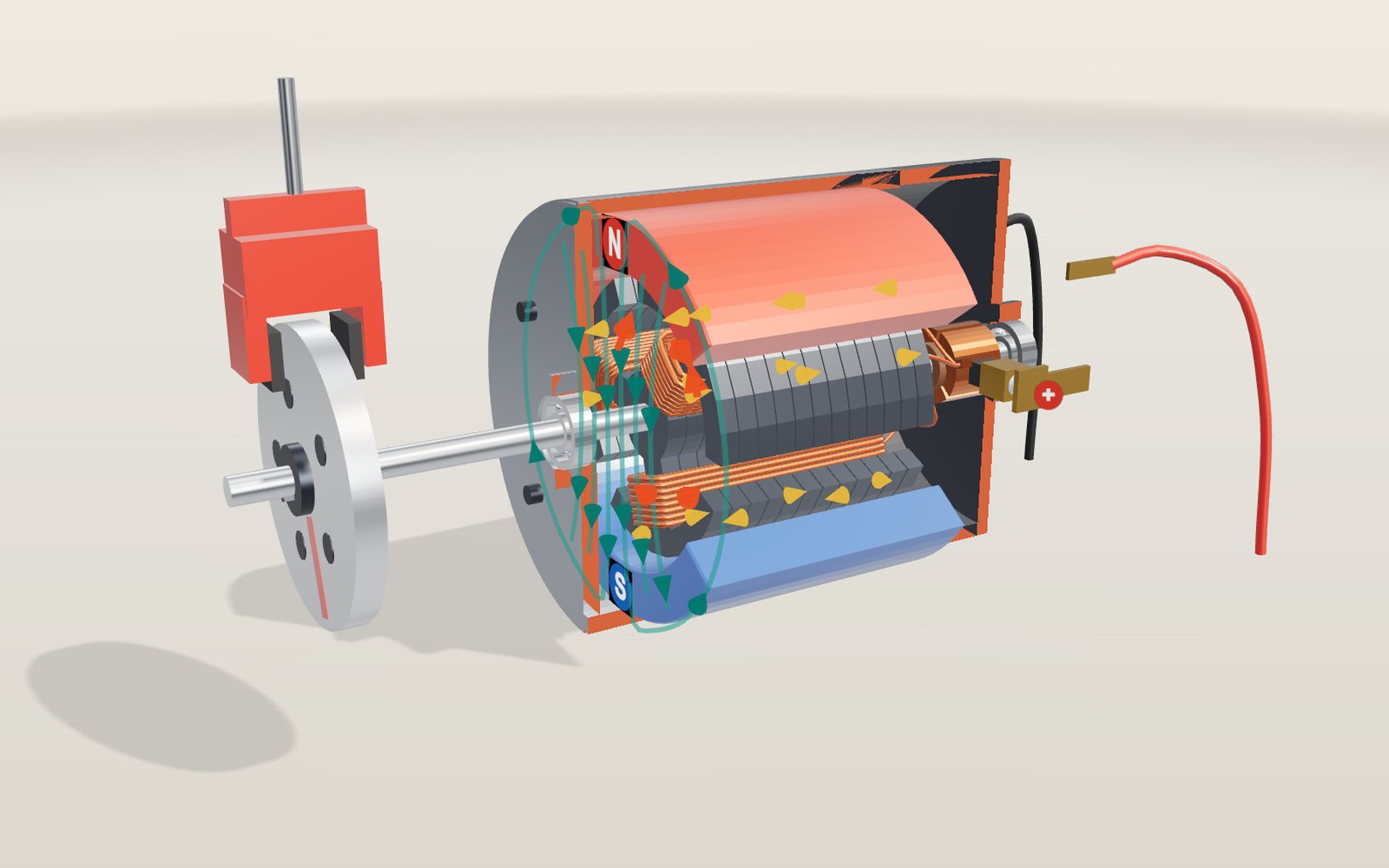
This device cannot show the 3D model. You can read the guide steps below as text.
1 / 17 A small DC motor, cut openThe near half of the case and the end cap has been cut away, and the red edges show the cut. Inside, a three-pole armature turns between two magnets. This is one of eight motors here: pick others from the Motor slider or the list under the controls.
Drag to turn. Scroll or pinch to zoom.
What the model shows
Pull the trigger on a cordless drill, switch on a ceiling fan or press the accelerator of an electric car, and something turns. The machines doing the turning look nothing alike. The cheapest has a split copper ring and two blocks of carbon. The car's has a chip that switches hundreds of amperes thousands of times a second. They all rest on the same push between a current and a magnetic field, first shown by Michael Faraday in 1821 with a wire hanging in a bowl of mercury.
This exhibit has eight motors. Pick one with the Motor slider or from the list under the controls, and the stage builds it:
- Brushed DC motor, the cut-open can motor in toys and car window lifts.
- Brushless DC (BLDC) outrunner, the kind that spins a drone propeller, with hall sensors and a driver board.
- Three-phase induction motor, the workhorse of pumps, fans and factories, with its squirrel cage rotor.
- Permanent-magnet synchronous motor, the electric-car motor with magnets buried in its rotor, an inverter on top and a reduction gear you can show with Drive unit.
- Stepper motor, the 3D printer motor that moves 1.8° per pulse, with a dial on the shaft.
- Servo, a small motor, gears and a sensor in one box that goes to the angle you ask for.
- Linear motor, a motor unrolled along a guideway, the idea behind maglev trains.
- Faraday's motor of 1821, a wire circling a magnet in mercury.
Each housing is cut in half so you can see inside, and red faces mark the cut. The readout in the corner changes with the motor: volts, amperes and rpm for the DC motors, frequency, slip and field speed for the induction motor, step angle and shaft angle for the stepper. More opens a small chart of the currents that make the field. Under the controls are the parts that do not fit in a corner: an equation box filled in with the live numbers, a graph for the motor on the stage, a larger chart of the phase currents and the field they add up to, six tasks, a table of efficiency classes, a comparison of the motors and a list of 41 cases from history and from machines you know.
The sliders change meaning with the motor. Voltage, Load and Magnet strength apply to most of them. PWM is the duty cycle of the switching for the DC motors and the pulse width for the servo. Frequency is the supply frequency for the induction motor, the inverter frequency for the electric-car motor and the linear motor, and the step rate for the stepper. Poles changes the winding of the AC motors. A slider that does nothing for the motor on the stage is greyed out.
Everything on screen turns slower than the numbers in the readout, otherwise it would be a blur. The DC motor is slowed 60 times, the drone motor 320 times, the induction motor 40 times. Slow motion slows it further.
Why a wire in a magnetic field moves
Everything in a motor rests on one fact. A wire carrying a current across a magnetic field is pushed sideways, at right angles both to the wire and to the field. The size of the push is
F = B × I × L
where B is the strength of the field in teslas, I is the current in amperes and L is the length of wire inside the field in metres. Take a wire 30 mm long in a field of 0.3 tesla, which is about what a ferrite magnet gives across a small air gap, and pass 1 ampere through it. The force is 0.3 × 1 × 0.03 = 0.009 newtons, about the weight of a gram. That is far too small to drive anything on its own.
So a motor uses many wires. Each coil is dozens of turns, and every turn has two long sides lying along the shaft, so the same small push is added up hundreds of times. The red arrows on the DC motor show the push on the two sides of each coil. The arrows grow with the current. They also depend on where the side is: a wire under a magnet feels the full field, a wire in the gap between magnets feels almost none.
Which way does the wire go? Turn on Left-hand rule and a hand appears over the motor. Point the first finger along the field, from north to south, and the second finger along the current; the thumb then points along the force. This is Fleming's left-hand rule for motors. In vector form it is F = I L × B, and the rule is a way of doing that cross product with your fingers. Reverse the current, as regenerative braking does, and the thumb turns round.
There is a second way to see the same thing. Current flowing around a coil turns its iron arm into an electromagnet with a north and a south end. That arm is pulled towards the magnet of the opposite pole and pushed away from the one of the same pole. Both descriptions give the same torque; they are two ways of counting the same forces. The AC motors on this stage are easier to follow the second way, so their coils turn red when they are north poles and blue when they are south.
Why the DC motor needs a commutator
Picture a single coil with steady current. Its arm becomes, say, a north pole, and it swings towards the south magnet. When it gets there the pull has nothing more to do. The arm overshoots a little, is pulled back and settles, like a compass needle. To keep it going, the current in the coil has to reverse just as the arm passes the magnet, so that the pole that was being pulled in is now pushed on.
That is the commutator's whole job. It is a rotary switch built into the shaft. Its segments turn with the coils, and the brushes stay still. As the shaft turns, each brush slides from one segment onto the next, and the connection to the coils changes over. In this model the segments are 112° wide with 8° gaps, and the two brushes sit on opposite sides. A brush crosses a gap every 60°, so the connections change six times per turn, and the current in each coil reverses once every half turn.
With Slow motion on, the DC motor slows down near each of those moments. For a few degrees the brush touches two segments at once and shorts the coil between them. The current in that coil has to die away and build up the other way in a very short time, and in a real motor this is where the small blue sparks at the brushes come from. The model draws a spark whenever a brush bridges a gap while current is flowing.
How three coils share the current
A motor with only two poles has a dead spot. If it stops with the coil square to the field, the force on both sides points straight outwards, there is no turning effect, and it will not start again on its own. Three poles avoid this. Whatever angle the rotor stops at, at least two of the coils sit where they can pull.
The three coils in this motor are joined end to end in a ring, and each joint goes to one commutator segment. With the brushes on two segments, the current has two ways to go: straight through one coil, or through the other two coils in series. The direct path has half the resistance, so it takes two thirds of the current, and each of the other two coils takes one third. When a brush bridges a gap, one coil is shorted and the other two share the current equally. The chart behind More draws these three coil currents against the rotor angle.
Work out the turning effect of all three coils at every angle and it never falls to zero. In this model's simplified picture it dips to about 77 % of its peak, six times per turn. That ripple is one reason cheap motors buzz. Motors with more poles and segments, five or seven or more, give smoother torque.
Back EMF, and why a motor draws less current when it runs
Measure the resistance of the coils in a small motor and you might find 2 ohms. Connect 12 volts and Ohm's law says 6 amperes should flow. That is true at the instant the motor starts. Once it is turning, the current drops to a fraction of that. The reason is that a motor is also a generator. Coils moving through a magnetic field have a voltage induced in them, and that voltage opposes the supply. It is called the back EMF and is proportional to speed:
E = k × ω
where ω is the speed in radians per second and k is the motor constant. The supply voltage has to cover both the back EMF and the voltage lost in the resistance of the coils:
V = I × R + k × ω
The same constant k links current and torque:
T = k × I
In SI units the two k are the same number. One volt-second per radian is the same as one newton-metre per ampere, and both come from the same coils in the same field.
These two lines explain how the motor behaves. It speeds up until the torque k × I just balances the load. If the load grows, the motor slows down, the back EMF falls, more of the supply voltage drives current through the coils, and the torque rises to meet the load. Nothing in the motor measures the load. The speed settles on its own.
The numbers, worked out
The DC motor's constants are model values, chosen to be in the range of a small 12 volt hobby motor: R = 2.0 ohms, k = 0.020 newton-metres per ampere, and a rotor plus load disc with a moment of inertia J = 1.0 × 10⁻⁴ kg·m². Friction, the voltage dropped at the brushes and the inductance of the coils are left out. All the figures on this page were checked with a short script that ships with the exhibit.
| Supply | No-load speed | Stall torque | Stall current |
|---|---|---|---|
| 3 V | 1,432 rpm | 30 mN·m | 1.5 A |
| 6 V | 2,865 rpm | 60 mN·m | 3.0 A |
| 9 V | 4,297 rpm | 90 mN·m | 4.5 A |
| 12 V | 5,730 rpm | 120 mN·m | 6.0 A |
No-load speed. With no load the current is zero, so V = k × ω and ω = V / k. At 12 V that is 600 radians per second, or 5,730 rpm. Every volt adds 477.5 rpm.
Stall torque. Held still, the motor has no back EMF and the current is V / R. At 12 V that is 6 A, and the torque is 0.020 × 6 = 0.12 N·m, or 120 mN·m.
A working point. At 9 V with a 20 mN·m load the current is 0.020 / 0.020 = 1 A. The back EMF is 9 − 1 × 2 = 7 V, so the speed is 7 / 0.020 = 350 rad/s, or 3,342 rpm. The supply puts in 9 W, the shaft gives out 0.020 × 350 = 7 W, and the efficiency is 77.8 %. The other 2 W heats the coils.
A heavier load. At 12 V and 80 mN·m the current is 4 A, the back EMF is 12 − 4 × 2 = 4 V, and the motor turns at 1,910 rpm. At 12 V and 20 mN·m it runs at 4,775 rpm on 1 A.
Most power. Output power is torque times speed, and it is largest halfway down the line, at half the no-load speed and half the stall torque. At 12 V that is 60 mN·m at 2,865 rpm, giving 18 W out of 36 W in. The efficiency there is exactly 50 %, so motors are normally run well above that speed.
Stronger magnets, more turns. Magnet strength and Coil turns both scale k. A magnet 1.5 times stronger lowers the no-load speed at 12 V to 3,820 rpm but raises the stall torque to 180 mN·m: the motor becomes slower and stronger. Doubling the turns with the same amount of copper doubles k too, but the wire is half as thick and twice as long, so R grows four times. The no-load speed halves to 2,865 rpm and the stall torque also halves, to 60 mN·m. That is why motor makers sell the same frame with several windings: one for a high voltage and low current, one for the reverse.
PWM. The PWM slider switches the supply on and off very fast and keeps it on for a share of the time. The motor's inductance smooths the pulses, so it behaves as if fed the average voltage. At 60 % on 12 V it runs as on 7.2 V. Almost every battery-powered motor is controlled this way, because a switch that is fully on or fully off wastes very little power.
How fast it gets there. The speed settles with a time constant J × R / k² = 0.5 s in the model. A real motor of this size, without a heavy disc on it, settles in a few hundredths of a second.
On the graph under the controls, torque runs across and speed up. For a given voltage the motor can only run on a straight line from the no-load speed to the stall torque. The red dashed line is the load, and the motor runs where they cross. Raise the voltage and the line moves outwards; raise the load past the stall torque and the lines never cross, which is how small motors burn out when something jams them.
Turned backwards: regenerative braking
A motor and a generator are the same machine. When the load pushes the shaft faster than the supply alone would turn it, the back EMF becomes larger than the supply voltage, and the current flows the other way: out of the motor and into the battery. The torque reverses with it, so the machine now brakes whatever is driving it.
Turn on Regenerative braking with the DC motor at 12 V and a load of 40 mN·m. The load now drives the shaft instead of holding it back. The current settles at −2 A, the speed at 7,639 rpm, and the battery takes 12 × 2 = 24 W while the shaft puts in 0.04 × 800 = 32 W. The 8 W difference warms the coils. The orange current arrows run the other way round the coils, the red force arrows point backwards, and the thumb of the left hand turns round.
Electric cars, trains and lifts all do this. On the electric-car motor, try the task under the controls: brake a 2,000 kg car from 100 km/h at 3 m/s² and see how much of its 214 Wh of kinetic energy goes back into the battery. The motor can take only as much braking torque as the Load slider allows, and no more than its power limit at high speed, so the friction brakes cover the rest. With 200 N·m allowed, the model recovers about 170 Wh, about 79 %. With regenerative braking off, all of it becomes heat in the brake discs. KONE's lift brochures describe the same idea for elevators: a heavy car going down, or a light car going up, drives the motor, and a regenerative drive feeds the energy back.
Brushless DC: a chip instead of brushes
Brushes wear, spark and limit speed. Take them away and something else has to know when to switch each coil. In 1962 T. G. Wilson and P. H. Trickey described the three things that job needs: sense where the rotor is, choose the switch, and switch. Transistors made it possible. The result is the brushless DC motor, which is really a permanent-magnet AC motor with its own switching electronics.
The motor on the stage is an outrunner of the kind used on drones. 12 coils sit on a fixed stator, and a bell carrying 14 magnets turns around the outside, so the propeller bolts straight on. The 14 magnets make seven pairs of poles, so the current pattern repeats seven times for each turn of the propeller. Three hall sensors in the slot openings at the back feel each magnet pass. They sit 120 electrical degrees apart, which on this motor is 120 / 7 ≈ 17.1° of shaft rotation. Their three on-off signals make six combinations, one for each 60° of the electrical cycle, and the driver board uses them to pick which two of the three phases get the battery and in which direction.
That is six-step commutation, and the More chart shows its currents as square steps. Watch the coils: at any moment eight of the twelve are lit, red for north and blue for south, and the pattern steps round just ahead of the magnets so it always pulls them on. The purple arrows on the teeth show the same pattern. The readout's Hall sensors row shows the code the driver is reading.
Electrically the motor behaves like the brushed one: V = I × R + k × ω still holds. Hobby motors are sold by their KV, the no-load rpm per volt. The model uses KV 920, so k = 60 / (2π × 920) ≈ 0.0104 V·s/rad, with 0.12 Ω of winding resistance. At 14.8 V and 60 % PWM with a 0.1 N·m load it turns at 7,051 rpm and draws 10.1 A with 82 % efficiency in the model.
A computer case fan works the same way with fewer parts. Noctua's NF-A12x25 has a single-phase motor with four poles and four slots, turns at up to 2,000 rpm on 1.2 W, and follows the PWM signal from the motherboard: 450 rpm at 20 % duty, and it stops at 0 %.
Three phases make a field that turns
The induction motor has no brushes, no magnets and no switching electronics, and still it keeps turning. The trick is in the stator. Its slots carry three alternating currents from the mains, each one a third of a cycle behind the last. Phase A peaks, then B, then C, then A again.
Each phase on its own makes a field that only pulses in and out along one direction. The three phases are wound with their axes 120 electrical degrees apart, and when you add up three such pulsing fields, each a third of a cycle late and a third of a turn round, the sum has a constant size and turns at a steady speed. The chart under the controls shows this: on the left the three currents over one cycle, on the right three arrows for the phases and a purple arrow for their sum, going round. In the model the slots are coloured by the current in them at that moment, and the purple arrows on the stator teeth show the poles of the field moving round the bore. Pick 2 poles to see a single north and south chase each other round; with 4 poles there are two of each, and the field turns half as fast.
How fast? In one cycle of the supply the field moves on by one pair of poles. With p poles the field makes 2/p turns per cycle, so in revolutions per minute
n_s = 120 × f / p
| Poles | 50 Hz | 60 Hz |
|---|---|---|
| 2 | 3,000 rpm | 3,600 rpm |
| 4 | 1,500 rpm | 1,800 rpm |
| 6 | 1,000 rpm | 1,200 rpm |
| 8 | 750 rpm | 900 rpm |
That is the synchronous speed, shown in the readout as Field speed. Galileo Ferraris built a two-phase motor on this idea in 1885, and Nikola Tesla's patent of 1888 describes one too. Mikhail Dolivo-Dobrovolsky at AEG had a three-phase motor with a cage rotor running at the start of 1889, and that is the design on the stage.
Slip: why the cage always lags
The rotor of an induction motor is a stack of steel sheets with aluminium bars cast through it near the surface, joined at both ends by rings. Without the iron it would look like a hamster wheel, hence squirrel cage. Nothing is connected to it.
When the field sweeps past the bars it induces a voltage in them, and because the end rings short them, currents flow. Those currents sit in the field and feel the force F = B × I × L, and that force drags the rotor after the field. But if the rotor ever caught up, the field would no longer sweep past the bars, nothing would be induced and there would be no force. So the rotor always runs a little slower than the field. The difference, as a share of the field speed, is the slip:
s = (n_s − n) / n_s
The model is a 4 kW, four-pole, 400 V motor. With its rated load of 26.5 N·m it turns at 1,451 rpm against a field of 1,500, a slip of 3.3 %, and draws 7.2 A. In the model the cage bars brighten where current is induced, and they glow more as the slip grows.
More load means more slip, more induced current and more torque, up to a point. The graph under the controls shows the full curve of torque against speed. From standstill the torque is 45 N·m and the current 47.6 A, more than six times the running current, which is why big motors are started with a soft starter or an inverter. As the motor speeds up the torque rises to a peak of 88 N·m near 1,130 rpm, then falls steeply to zero at the field speed. The motor runs on that steep last part, where a small change of speed makes a large change of torque, so the speed hardly moves with the load: 1,482 rpm at 10 N·m, 1,451 at 26.5. Push the load past the peak and the motor stalls.
Drive the shaft faster than the field, with Regenerative braking on, and the slip turns negative. The bars cut the field the other way, the torque reverses and the machine generates: at 20 N·m of driving torque it runs at 1,532 rpm, 2.2 % above the field speed, and feeds 2.89 kW back to the grid.
Frequency and poles set the speed
Plugged straight into the mains, an induction motor runs at nearly one speed. An inverter changes that. It turns the mains into direct current and then back into three phases of whatever frequency it likes. To keep the field strength the same it lowers the voltage in step with the frequency, which is the V/f rule the model uses up to 50 Hz.
Set Frequency to 30 Hz with four poles and the field turns at 900 rpm; under the rated load the rotor follows at 849 rpm. Pumps and fans gain the most from this. Their power falls steeply with speed, so running a fan a little slower saves much more energy than closing a damper in front of it at full speed. The task asks you to make the motor turn at 1,000 rpm with at least 20 N·m of load: with four poles you need about 34.6 Hz, with six poles about 50.8 Hz.
Poles change the speed in big steps instead. The slider rewinds the stator on the spot. Some motors really do this: a pole-changing winding can be reconnected from four poles to eight, so a fan has two speeds without any electronics.
The electric-car motor: magnets in the rotor
Most electric cars and hybrids use a permanent-magnet synchronous motor. Its stator looks like the induction motor's, with 48 slots and three phases. The rotor is different: inside the steel stack there are pockets with strong magnets in them, two per pole in a V shape. With eight poles there are 16 magnets. The rotor follows the turning field exactly, with no slip, because its own magnets lock onto the field's poles. It is synchronous.
So the speed is fixed by the inverter frequency, n = 120 × f / p. At 200 Hz with 8 poles that is 3,000 rpm. The load does not change the speed; it changes the angle by which the rotor's poles trail the field's, the load angle in the readout. With no load the two line up. With 100 N·m the rotor trails by about 17 electrical degrees. Raise the load past what the motor can give at that speed and it pulls out of step, loses its grip on the field and stops. In a car the inverter never lets that happen: it measures the rotor position and sets the current so that the field always leads by the right amount.
Burying the magnets in V-shaped pockets has two benefits. They are held safely at high speed, and the steel between and around them makes the rotor easier to magnetise along some directions than others. That gives a second kind of torque, reluctance torque, from the iron trying to line up with the field. It is why such motors are called interior permanent-magnet machines.
The magnets themselves are mostly neodymium-iron-boron. Masato Sagawa and colleagues published the material in 1984 with a remanence of 1.23 T and an energy product of 290 kJ/m³, far stronger than the ferrite in a toy motor. That is what makes a 50 kW motor small enough to fit between the wheels.
The model's motor gives up to 300 N·m from standstill to 4,775 rpm at 400 V, which is 150 kW. Above that the back EMF of the magnets approaches what the battery can push against, and the inverter has to send part of its current to weaken the magnets' field. That is field weakening: the torque falls as speed rises so that the power stays at about 150 kW, up to 16,000 rpm. A higher battery voltage moves the corner up; a stronger magnet gives more torque but reaches the corner sooner.
Efficiency, the map and the gearbox
Where does the motor lose power? Copper losses grow with the square of the current, so with the square of the torque. Iron losses come from the field reversing in the steel hundreds of times a second and grow with speed. Windage and bearing losses grow with speed too. Each corner of the operating range has its own enemy: copper at high torque, iron and field weakening at high speed. The best efficiency lies in the middle.
The graph under the controls for the electric-car motor is an efficiency map: speed across, torque up, darker where the motor is more efficient, with the black line marking the most torque available at each speed. In the model the best point is 96.5 % at about 8,500 rpm and 165 N·m. Oak Ridge National Laboratory measured the 2012 Nissan Leaf's motor and found peak efficiency above 97 % between 5,000 and 9,000 rpm. The task asks you to find the model's best point with Frequency and Load.
Turn on Drive unit to see what connects the motor to the wheels. Two stages of gears, 18 to 60 and then 17 to 46, slow it down by about 9 times and multiply the torque by the same amount. The second gear is the crown wheel of the differential, which lets the two wheels turn at different speeds in a corner. At 6,000 rpm and with 0.35 m wheels the car is doing about 88 km/h. The gearbox is why EV motors are built for high speed: the faster a motor turns for the same power, the less torque it needs, and the smaller and lighter it can be. Oak Ridge's tests show the trend: the 2004 Prius motor gave 400 N·m and 50 kW up to 6,000 rpm, while the 2010 motor gave 205 N·m and 60 kW up to 13,500 rpm.
The stepper motor: one pulse, one step
A 3D printer has to put its nozzle within a fraction of a millimetre of where the file says, thousands of times a minute, without measuring where it is. It uses stepper motors. Each pulse from the driver moves the shaft by a fixed angle, and between pulses it holds still, so counting pulses is enough to know where it is.
The motor on the stage is a hybrid stepper of the common NEMA 17 size, drawn about twice life size. The rotor is two toothed steel cups with an axial magnet between them, so one cup is all north poles and the other all south. Each cup has 50 teeth, and the two are offset by half a tooth. The stator has eight poles with small teeth on their faces, wound as two phases, A and B. Energise the phases in turn and the rotor's teeth jump to line up with the stator teeth that are now strongest.
Two phases, four combinations of current direction per electrical cycle, and fifty teeth: 4 × 50 = 200 full steps per turn, 1.8° each. In half-step mode the driver adds the in-between states with one phase off, giving 400 steps of 0.9°. In microstepping the two currents follow a sine and a cosine, and the rotor can stop between teeth; at 1/16 step it moves 0.1125° per pulse. The step buttons in the lab send single pulses, and the dial on the front shows the result. The task asks for exactly 90°, which is 50 full steps.
Steppers have a weakness: nothing checks that a step really happened. Each step needs the current in a coil to build up, and the coil's inductance slows that down, so the torque a stepper can deliver falls as the step rate rises. The graph shows this pull-out curve. Above it the rotor cannot keep up and misses steps, and the controller never knows. In the model, with 0.2 N·m of load at 24 V the motor keeps up to about 834 full steps per second; at 48 V the current builds faster and it keeps up to about 1,668. That is why printer drivers run at 24 V or more, and why a print that hits an obstacle ends up shifted sideways. A common NEMA 17 motor is rated at 42 N·cm of holding torque at 1.7 A per phase.
The servo: a motor that checks its own work
A servo solves the stepper's problem with feedback. Inside a hobby servo there is a small brushed DC motor, a train of plastic gears that slows it down and makes it stronger, a potentiometer turned by the output shaft, and a control board. The board receives a pulse every 20 ms. The width of the pulse is the command: 1.5 ms means the middle, 1.0 ms means 90° one way, 2.0 ms 90° the other. The board compares the pulse with the potentiometer and drives the motor with a voltage that grows with the difference, until the difference is gone. Push on the horn and the board pushes back.
TowerPro's SG90, the 9 g servo found in countless school robots, gives 1.8 kg·cm of torque at 4.8 V and moves 60° in 0.1 s. The model behaves like a small DC motor with those figures seen from the output shaft, and a proportional controller with a little damping. Change PWM to 2.0 ms and the graph shows the angle racing up to +90° and settling; add Load and a small steady error remains, because the controller needs some error to produce the voltage that holds the load.
The same loop, with an encoder instead of a potentiometer and a three-phase motor instead of a brushed one, runs every industrial robot arm and CNC axis. Electric-car inverters close the same kind of loop on the current many thousand times a second.
The linear motor: unrolled flat
Cut a motor along its length and unroll it, and the stator becomes a long strip and the field that turned now travels along it. Put the magnets on a vehicle, and the vehicle is carried along at the speed of the field. That is a linear synchronous motor. Its speed is set by the frequency and the pole pitch τ, the distance from one pole of the travelling field to the next:
v = 2 × τ × f
The model uses a pole pitch of 0.25 m, so 100 Hz gives 50 m/s, or 180 km/h, and 300 Hz gives 540 km/h. On the stage the guideway runs away from you and is cut across, so you can see the long stator under both edges, the cable in its slots coloured by the current, and the magnets on the vehicle's skirts below. The vehicle stays in the middle of the screen while the guideway streams past, and the purple arrows show that the field stays locked to the magnets.
Maglev trains use this. Japan's superconducting maglev reached 517 km/h with the ML-500 test vehicle in 1979, and a seven-car L0 train reached 603 km/h on the Yamanashi line on 21 April 2015, still the record for a train. The same idea, at a smaller scale, moves the stages of chip-making machines and some factory conveyors.
Faraday's motor of 1821
In 1820 Hans Christian Ørsted showed that a current in a wire deflects a compass needle. Michael Faraday, then an assistant at the Royal Institution in London, set out to repeat the experiment for a review of the subject. On 3 September 1821, in the basement laboratory, he made a wire carrying a current turn continuously around a magnet, and wrote it up as "On some new electro-magnetical motions". His notebook describes the setup: a deep basin with wax at the bottom, filled with mercury, a magnet stuck upright in the wax with its pole just above the surface, and a wire hanging into the mercury.
The last motor on the stage rebuilds that. The current runs from a voltaic pile up the brass stand, down the hanging wire, through the mercury and back. Around the magnet's top the field spreads out sideways, so the wire, carrying current downwards through it, is pushed sideways too, always at right angles, and so it goes round and round the pole. Flip the magnet and it circles the other way. In the model the speed simply grows with the current, because the drag of the mercury grows with the speed. The Royal Institution still has one of Faraday's mercury baths from 1822, 247 mm tall.
Faraday's device turned but could not drive anything. It was a demonstration that electricity and magnetism could make continuous motion, and the start of everything else on this stage.
Efficiency classes and why they matter
Motors and the machines they drive use more electricity than anything else. The International Energy Agency put the share at more than 40 % of the world's electricity in 2011, and estimated that about 25 % of that could be saved cost-effectively. A 2025 brief from the IEA's 4E motor systems programme puts it at 53 % in 2023: 72 % of the electricity used in industry and 36 % in buildings. In the EU the motors covered by the ecodesign rules numbered 380 million in 2020 and used 1,326 TWh a year, 56 % of the EU's final electricity use.
So small differences in efficiency add up. The international standard IEC 60034-30-1, published in 2014, sorts line-operated AC motors into efficiency classes, IE1 to IE4 (a 2025 edition adds IE5). For a four-pole, 4 kW, 50 Hz motor the EU tables give 86.6 % for IE2, 88.6 % for IE3 and 91.1 % for IE4. Since 1 July 2021, three-phase motors from 0.75 to 1,000 kW sold in the EU must reach IE3, and since 1 July 2023 those from 75 to 200 kW with two, four or six poles must reach IE4. In the United States, motors made from 1 June 2016 must meet the NEMA Premium level, which matches IE3.
The model induction motor reaches 90.1 % at its rated load, inside the IE3 band. Lowering losses by a point or two takes more copper, better steel and tighter gaps, which is why higher-class motors cost more to buy and less to run.
What this model leaves out
The motors are drawn the way their parts are arranged, but not to one scale: the DC motor and the stepper are drawn several times larger than real ones so they are easy to see, and the induction and electric-car motors are drawn smaller. The electrical numbers are model values chosen to behave like real motors of each kind, not the figures of any one product. The case list quotes real products with their sources.
The DC model ignores friction, brush voltage and inductance. The brushless model treats the drag of the propeller as a fixed torque. The induction model uses the textbook equivalent circuit with fixed resistances, so it ignores how the rotor bars' resistance rises with frequency at start, and the magnetising current is simplified. The electric-car motor is a map of torque limits and losses rather than a full field calculation, and its load angle is drawn from a simple sine law. The stepper's rotor responds to each step with a damped spring shown in slow motion. The linear motor's pole pitch of 0.25 m is a model value. The force and field arrows are drawn to be readable, not to scale.
Where the electric motor came from
After Faraday's rotations of 1821, Peter Barlow built a star-shaped wheel that spun in mercury between magnet poles in 1822, the first rotating device driven by electromagnetism. William Sturgeon built the electromagnet in 1825, and with it real motors became possible. In May 1834 Moritz Jacobi in Königsberg finished the first rotating motor with a useful output; its record stood for four years until his own second motor drove a boat with 14 people across a river in 1838.
Thomas Davenport, a blacksmith from Vermont, began experimenting with an electromagnet in 1833 and on 25 February 1837 received US patent 132, the first patent for an electric motor. His model has four electromagnets turning inside a ring of permanent magnets, switched by a commutator, and is said to have reached about 1,000 rpm and 4.5 watts. But batteries were expensive and steam was cheap, and these early motors went nowhere.
What changed things was the generator. Werner Siemens laid windings in slots in 1856, as nearly every machine still does, and developed the dynamo in 1866 and 1867. Zénobe Gramme's ring armature of 1871 gave smooth direct current, Friedrich von Hefner-Alteneck's drum armature improved it, and in 1873 Auguste Pellerin proposed splitting the iron into insulated sheets. Cheap current from dynamos made motors worth building. In 1879 Siemens & Halske ran an electric locomotive at the Berlin trade fair: 150 V, 2.2 kW, 954 kg, 7 km/h, carrying about 90,000 visitors around a 300 m oval.
Alternating current needed its own motor. Ferraris built a two-phase induction motor in 1885, but believed its efficiency could never pass 50 %. Tesla filed his first patents for a two-phase AC system in 1887; US patent 381,968 for an electro-magnetic motor was granted on 1 May 1888. Dolivo-Dobrovolsky's three-phase cage motor followed in 1889, and in 1891 AEG and Oerlikon sent three-phase power 175 km from Lauffen to Frankfurt at up to 25 kV, and three-phase motors began to spread through industry.
The 20th century added electronics. Wilson and Trickey's solid-state commutation of 1962 led to brushless motors, the Nd-Fe-B magnet of 1984 made small powerful permanent-magnet motors possible, and power transistors put inverters in everything from lifts to cars. In 1996 KONE launched a lift with no machine room, driven by a flat permanent-magnet motor that fits in the shaft.
Questions
Why does a DC motor need a commutator?
A coil with steady current turns until its pole lines up with the opposite magnet and then stops. The commutator reverses the current in each coil just as it passes that point, so the coil keeps being pushed the same way. In this three-pole motor the connections change six times per turn and each coil's current reverses every half turn.
What is back EMF?
It is the voltage a motor generates because its coils are moving through a magnetic field. It is proportional to speed (E = k × ω) and opposes the supply. It is why a running motor draws much less current than a stalled one.
Why does a motor draw so much current when it starts or jams?
At standstill there is no back EMF, so only the resistance of the coils limits the current. In the DC model that is 12 V / 2 Ω = 6 A at stall, against 1 A when running at a 20 mN·m load. The induction model draws 47.6 A at start against 7.2 A at rated load.
Why does a motor slow down under load?
The torque comes from the current (T = k × I). To give more torque the motor needs more current, and with a fixed supply voltage it only gets more current if the back EMF drops, which means turning slower. An induction motor slows down for a similar reason: it needs more slip to induce more current in its cage.
What does Fleming's left-hand rule tell you?
The direction of the force on a wire. Hold the first finger along the field (north to south), the second finger along the current, and the thumb points along the force. The right-hand rule, with the same fingers, gives the current induced in a generator.
Why do brushed motors have three or more poles?
A two-pole rotor has a position where the forces push straight outwards and give no turn, so it may not start. With three poles at least two coils can always pull, and the torque never falls to zero.
Can a motor work as a generator?
Yes. Turn the shaft faster than the supply would drive it and the current reverses. The DC model at 12 V, driven with 40 mN·m, turns at 7,639 rpm and charges the battery with 24 W. Electric cars use this to recover energy when braking.
What is slip?
How far an induction motor's rotor lags behind the turning field, as a share of the field speed. It has to lag, because only then does the field sweep past the cage bars and induce the currents that make torque. The model's 4 kW motor runs at 1,451 rpm against a field of 1,500, a slip of 3.3 %.
How do I work out an induction motor's poles from its nameplate?
Find the synchronous speed just above the rated speed: 120 × f / p. A 50 Hz motor rated at 1,450 rpm must have a field of 1,500 rpm, so it has four poles and a slip of about 3.3 %. A 60 Hz motor at 1,750 rpm also has four poles.
Why is a BLDC motor called DC when its coils carry alternating current?
Because it runs from a DC supply and behaves like a brushed DC motor: speed rises with voltage and torque with current. The driver chip and hall sensors do the commutator's job, switching the battery onto the three phases in six steps per electrical cycle, so each coil sees current in both directions.
Why do electric cars use a gearbox if the motor gives torque from standstill?
Because a motor that turns faster for the same power needs less torque, and less torque means less copper, steel and magnet. A reduction of about 9 to 1 lets a motor spinning at 10,000 rpm or more drive wheels turning at about a tenth of that.
Why does a stepper motor lose steps?
Each step needs the coil current to build up, and the coil's inductance slows that, so the available torque falls as the step rate rises. If the load is more than the pull-out torque at that rate, the rotor slips back a tooth and the controller never notices, because a stepper normally has no position sensor.
How does a servo know its angle?
A potentiometer on the output shaft turns with it and gives a voltage that depends on the angle. The board compares that with the pulse width it receives, 1.0 to 2.0 ms in every 20 ms frame, and drives the motor until they agree.
What do the IE efficiency classes mean?
They are levels set by IEC 60034-30-1 for the efficiency of AC motors at full load, IE1 the lowest. For a four-pole, 4 kW, 50 Hz motor the EU minimums are 86.6 % for IE2, 88.6 % for IE3 and 91.1 % for IE4. Most three-phase motors sold in the EU have had to reach IE3 since July 2021.
Terms
- Armature: the rotating part of a DC motor, with the iron core and the coils.
- Commutator: the segmented copper ring on a DC motor's shaft that switches the current between coils.
- Brush: a carbon block that slides on the commutator and carries current in or out.
- Back EMF: the voltage a turning motor generates, opposing the supply.
- Motor constant (k): volts of back EMF per radian per second, equal to newton-metres of torque per ampere.
- KV: a hobby motor's no-load speed in rpm per volt.
- Stator: the fixed part of a motor; in AC motors it carries the windings.
- Rotor: the part that turns.
- Hall sensor: a chip that gives a signal when a magnetic pole passes.
- Six-step commutation: switching a three-phase motor's supply in six steps per electrical cycle, two phases at a time.
- Synchronous speed: the speed of the turning field, 120 × f / p rpm.
- Slip: how far an induction motor's rotor lags the field, as a share of the field speed.
- Squirrel cage: an induction motor rotor of bars joined by end rings.
- Load angle: how far a synchronous motor's rotor poles trail the field's poles.
- Field weakening: using part of the current to oppose the magnets' field so the motor can run faster than its base speed.
- Inverter: electronics that turn DC into AC of any frequency and back.
- Step angle: how far a stepper turns per pulse; 1.8° for a 200-step motor.
- Pull-out torque: the most torque a stepper can give at a step rate without missing steps.
- Pole pitch (τ): the distance between neighbouring poles of a linear motor's travelling field.
- Regenerative braking: braking by running the motor as a generator and storing the energy.
Sources
- Royal Institution, The birth of electric motion (2021). https://www.rigb.org/explore-science/explore/blog/birth-electric-motion (checked 18 October 2026)
- Royal Institution, Michael Faraday's electric magnetic rotation apparatus (motor). https://www.rigb.org/explore-science/explore/collection/michael-faradays-electric-magnetic-rotation-apparatus-motor (checked 18 October 2026)
- M. Faraday, On some new electro-magnetical motions, and on the theory of magnetism, Quarterly Journal of Science 12 (1821), scan held by Museu Faraday, Instituto Superior Técnico. https://museufaraday.ist.utl.pt/HistTecnology/Faraday_motor.pdf (checked 18 October 2026)
- American Physical Society, APS News: September 4, 1821 and August 29, 1831: Faraday and Electromagnetism. https://www.aps.org/apsnews/2001/08/faraday-electromagnetism (checked 16 October 2026)
- German Patent and Trade Mark Office (DPMA), First patent for an electric motor: Thomas Davenport. https://www.dpma.de/english/our_office/publications/milestones/greatinventors/thomasdavenport/index.html (checked 18 October 2026)
- M. Doppelbauer, The invention of the electric motor 1800-1854, Karlsruhe Institute of Technology. https://www.eti.kit.edu/english/1376.php (checked 18 October 2026)
- M. Doppelbauer, The invention of the electric motor 1856-1893, Karlsruhe Institute of Technology. https://www.eti.kit.edu/english/1390.php (checked 18 October 2026)
- Karlsruhe Institute of Technology, Jacobi's first real electric motor. https://www.eti.kit.edu/english/1382.php (checked 18 October 2026)
- Deutsches Museum, Elektrische Lokomotive, Siemens & Halske, inventory no. 3720. https://digital.deutsches-museum.de/en/digital-catalogue/collection-object/3720/ (checked 18 October 2026)
- N. Tesla, Electro-magnetic motor, US patent 381,968 (1 May 1888). https://patents.google.com/patent/US381968A/en (checked 18 October 2026)
- T. G. Wilson and P. H. Trickey, D-C machine with solid-state commutation, Electrical Engineering 81 (1962). https://doi.org/10.1109/EE.1962.6446586 (checked 18 October 2026)
- M. Sagawa et al., New material for permanent magnets on a base of Nd and Fe, Journal of Applied Physics 55, 2083 (1984). https://doi.org/10.1063/1.333572 (checked 18 October 2026)
- R. H. Staunton et al., Evaluation of 2004 Toyota Prius Hybrid Electric Drive System, ORNL/TM-2006/423. https://www.osti.gov/biblio/890029 (checked 18 October 2026)
- T. A. Burress et al., Evaluation of the 2010 Toyota Prius Hybrid Synergy Drive System, Oak Ridge National Laboratory (2011). https://info.ornl.gov/sites/publications/files/pub26762.pdf (checked 18 October 2026)
- T. Burress, Benchmarking State-of-the-Art Technologies, US DOE Vehicle Technologies Annual Merit Review (2013). https://www.energy.gov/sites/prod/files/2014/03/f13/ape006_burress_2013_o.pdf (checked 18 October 2026)
- Central Japan Railway Company, Superconducting Maglev (SCMAGLEV). https://global.jr-central.co.jp/en/company/_pdf/superconducting_maglev.pdf (checked 18 October 2026)
- KONE Corporation, History. https://www.kone.com/global/en/company/history.html (checked 18 October 2026)
- KONE Corporation, KONE S MonoSpace brochure (2017). https://www.kone.vn/en/Images/brochure-kone-s-monospace._tcm149-18330.pdf (checked 18 October 2026)
- TowerPro, SG90 Digital (specifications). https://towerpro.com.tw/product/sg90-7 (checked 18 October 2026)
- StepperOnline, Nema 17 stepper motors. https://www.omc-stepperonline.com/nema-17-stepper-motor (checked 18 October 2026)
- Noctua, NF-A12x25 PWM specifications. https://www.noctua.at/en/products/nf-a12x25-pwm/specifications (checked 18 October 2026)
- Noctua, PWM specifications white paper. https://cdn.noctua.at/media/Noctua_PWM_specifications_white_paper.pdf (checked 18 October 2026)
- NASA Jet Propulsion Laboratory, Ingenuity Mars Helicopter Landing Press Kit: Spacecraft. https://www.jpl.nasa.gov/news/press_kits/ingenuity/landing/mission/spacecraft (checked 18 October 2026)
- IEC, IEC 60034-30-1:2014, Efficiency classes of line operated AC motors (IE code). https://webstore.iec.ch/en/publication/136 (checked 18 October 2026)
- ABB, Technical note: IEC 60034-30-1 standard on efficiency classes for low voltage AC motors (2018). https://library.e.abb.com/public/db64d153e3c346938e18916e66fb1d0d/9AKK107319%20EN%2005-2018_20848_ABB_Technical_note_IEC_60034_30_1.pdf (checked 18 October 2026)
- Commission Regulation (EU) 2019/1781, ecodesign requirements for electric motors and variable speed drives. https://eur-lex.europa.eu/eli/reg/2019/1781/oj (checked 18 October 2026)
- European Commission, Energy Efficient Products: Electric motors. https://energy-efficient-products.ec.europa.eu/product-list/electric-motors_en (checked 18 October 2026)
- IEA (P. Waide and C. U. Brunner), Energy-Efficiency Policy Opportunities for Electric Motor-Driven Systems (2011). https://www.iea.org/reports/energy-efficiency-policy-opportunities-for-electric-motor-driven-systems (checked 18 October 2026)
- IEA 4E EMSA, Electric motor systems: a key element on the way to global net zero (2025). https://www.iea-4e.org/emsa/news/electric-motor-systems-a-key-element-on-the-way-to-global-net-zero/ (checked 18 October 2026)
- US Department of Energy, Energy Conservation Standards for Electric Motors, Federal Register 88 FR 36066 (1 June 2023). https://www.federalregister.gov/documents/2023/06/01/2023-10019/energy-conservation-program-energy-conservation-standards-for-electric-motors (checked 18 October 2026)
- Georgia State University, HyperPhysics, DC Motor. http://hyperphysics.phy-astr.gsu.edu/hbase/magnetic/motdc.html (checked 16 October 2026)
- Georgia State University, HyperPhysics, Commutator and Brushes on DC Motor. http://hyperphysics.phy-astr.gsu.edu/hbase/magnetic/comtat.html (checked 16 October 2026)
- Georgia State University, HyperPhysics, Magnetic Force on a Current-Carrying Wire. http://hyperphysics.phy-astr.gsu.edu/hbase/magnetic/forwir.html (checked 16 October 2026)
- The model's numbers come from the formulas on this page with model values (DC motor: R = 2.0 Ω, k = 0.020 N·m/A, J = 1.0 × 10⁻⁴ kg·m²; induction motor: 4 kW, 4 poles, 400 V; EV motor: 300 N·m, 150 kW at 400 V).
More exhibits
How lightning and thunder work
A lightning channel heats the air to about five times the temperature of the Sun’s surface, and its thunder needs about 3 seconds to cover each kilometre to you.
How electricity gets to your home
Electricity leaves the power station at 345,000 volts and reaches the outlet at 220, because high voltage keeps the current, and the heat lost in the wires, small.
How a lithium-ion battery works: where the ions go on charge
Each time an 18650 cell charges, about 7 × 10²² lithium ions leave a metal oxide and squeeze in between sheets of graphite.
How a microwave oven works: the magnetron that makes the waves
The waves inside a microwave oven are 12.2 cm long, so without a turntable the hot spots in your food sit about 6 cm apart.
How a solar panel works
In full sun a 60-cell rooftop panel makes about 300 watts, and all of it comes from an electric field sitting inside each slice of silicon.
How a touchscreen works: how the glass finds your finger
Under the glass of a phone lies a grid of transparent electrodes, and your finger shows up as a small dip in the charge passing between them.