Loading the model
This device cannot show the 3D model. You can read the guide steps below as text.
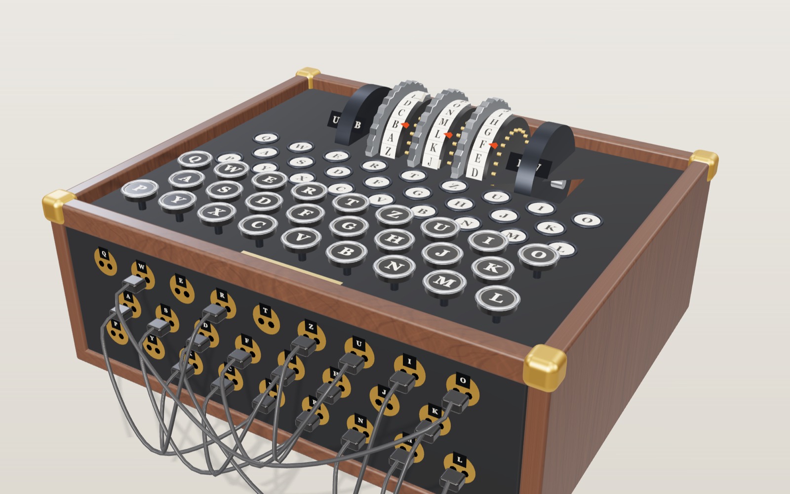
1 / 10 A real message from 1941 The machine is set to rotors II, IV and V, rings B U L, start position B L A and ten plug cables. It is typing a German army message sent on 7 July 1941, and the lamps spell out the plain German text: AUFKLXABTEILUNGXVONX...
Drag to turn. Scroll or pinch to zoom.
Guide Parts Controls
01 A real message from 1941 The machine is set to rotors II, IV and V, rings B U L, start position B L A and ten plug cables. It is typing a German army message sent on 7 July 1941, and the lamps spell out the plain German text: AUFKLXABTEILUNGXVONX...
02 Key in, lamp out Pressing a key does two things in order. The key first pushes the rotors on by one step, then closes a circuit from the battery to one lamp. Here the machine is reset to I-II-III at AAA and types HALLO.
03 The plugboard Before the current reaches the rotors it goes through the front sockets. A cable between A and V means A enters the rotors as V, and a V coming back lights the A lamp. Unplugged letters pass straight through.
04 Inside a rotor A rotor is a disc with 26 contacts on each face and 26 wires inside that join them in a scrambled order. With See inside on, the red wire is the one carrying the current for this key press.
05 Stepping and the double step Rotors here start at A D U and the machine types four letters. The windows read ADV, AEW, BFX, BFY. The middle rotor moves twice in a row because its own notch lets the pawl push it again, together with the left rotor.
06 The reflector On the far left the current meets the reflector, which joins the contacts in pairs and sends it back through all three rotors by a different route. This is why no letter can ever become itself.
07 One letter, start to finish From AAA, the A key lights B. The strip at the top lists every stop: key, plug, three rotors, reflector, three rotors again, plug and lamp. Red is the way in, blue is the way back.
08 Follow the current A light now runs along the path at walking pace. Watch it leave the A key, cross the plugboard, go right to left through the rotors, turn in the reflector and come back to the B lamp. The strip at the top lights each stop as it passes.
09 Decrypting is the same as encrypting Set the machine exactly as the sender did and type the cipher text. Because the reflector makes every connection reversible, the lamps show the original message. Type your own text, note the lamps, reset and type them back.
10 Four wheels for the U-boats The naval M4 of 1942 kept the same case. A thin reflector made room for a fourth wheel, Beta or Gamma, that never steps. The reflector tag now reads B thin and the fourth wheel. Set to Beta at A, it behaves exactly like the old reflector B.
Keyboard 26 keys in the German QWERTZ order. Pressing one first turns the rotors, then closes the circuit. Lampboard 26 small bulbs under lettered windows. The one that lights is the cipher letter. Plugboard Cables swap pairs of letters before and after the rotors. Ten cables were standard from 1939. Plug cables Each cable joins two sockets, so the swap works in both directions. Entry wheel Fixed plate that hands the current from the plugboard to the right rotor. On Enigma I it is wired A to A, B to B. Right rotor The fast rotor. It moves one step on every key press. Middle rotor Steps when the right rotor passes its notch, and once more on the next key (the double step). Left rotor The slow rotor. It moves only when the middle rotor passes its notch. Reflector Joins the 26 contacts in 13 pairs and sends the current back through the rotors. The Enigma I took reflector B, later C; A was the pre-war version. Battery A 4.5 volt flat battery inside the case lights the lamps. Top plate Holds keys and lamps. See inside makes it transparent. Wooden case About 34 × 28 × 15 cm. The machine weighs around 12 kg. Key levers Each key sits on a steel lever. Pressing it pushes the stepping pawls first and only then closes the lamp circuit. Alphabet rings The lettered tyres you read through the lid window. The ring setting turns the tyre against the wiring core, so the same letter in the window can mean a different wiring position. Thumbwheels Serrated wheels that stick out of the lid so the operator can set each rotor by hand. Tap one in the model to move that rotor on by one letter. Turnover notches A notch on the ring lets the pawl reach the next rotor. Rotors I to V have one notch, the naval rotors VI to VIII have two (at Z and M). Rotor contacts 26 spring pins on one face and 26 flat plates on the other. Pins of one rotor press on the plates of its neighbour. Rotor wiring The 26 wires inside each rotor and the 13 links in the reflector. Turn on See inside to see them. Window marks Fixed red marks at the top of each rotor. The letter level with the mark is the one shown in the lid window. Rotor axle One spindle carries the three rotors, the reflector and the entry wheel. Lifting a lever frees it so the rotors can be swapped. Plug sockets 26 brass socket plates on the front, one per letter, each with two holes of different sizes so a cable can swap both directions. Name plate The ENIGMA name plate on the top plate.