Loading the model
This device cannot show the 3D model. You can read the guide steps below as text.
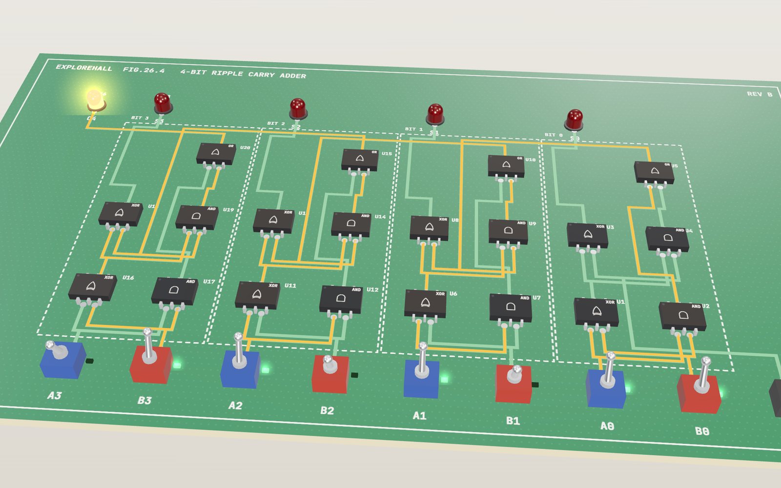
1 / 20 Two 4-bit numbers and five LEDs The front row holds two 4-bit numbers. Here A is 0111 (7) and B is 1001 (9). Watch the light run through 20 gates until the LEDs read 10000, which is 16. Tap any switch to change a bit, or pick another circuit with the Circuit slider.
Drag to turn. Scroll or pinch to zoom.
Guide Parts Controls
01 Two 4-bit numbers and five LEDs The front row holds two 4-bit numbers. Here A is 0111 (7) and B is 1001 (9). Watch the light run through 20 gates until the LEDs read 10000, which is 16. Tap any switch to change a bit, or pick another circuit with the Circuit slider.
02 A switch and a lamp Start with the simplest circuit. Switch X is joined to the LED by a jumper, so the LED shows exactly what the switch says: 1 is on, 0 is off.
03 The transistor is a switch too Now X drives the base of a transistor. A small current into the base lets a larger current flow through the other two legs, and the LED lights. In logic circuits a transistor is used only fully on or fully off.
04 Gates from transistors A gate is a few transistors wired so that the output follows a rule. AND gives 1 only when both inputs are 1. Choose NOT, OR or NOR under the model and compare the LED with the truth table.
05 NAND, the cheapest gate NAND is AND with the answer flipped. In CMOS it takes 4 transistors, two fewer than AND, and every other gate can be built from NANDs alone. Turn on Transistors per chip to see the counts.
06 XOR: one or the other, not both XOR gives 1 when its inputs differ. Its last row, 1 and 1 give 0, is the sum bit of 1 + 1 in binary, where the 1 moves to the next column.
07 The half adder An XOR and an AND fed by the same two switches. With A and B both 1, XOR gives sum 0 and AND gives carry 1, which reads 10, or 2. This pair adds two bits and nothing more.
08 The full adder A column in the middle of a sum has three inputs: two bits and a carry. A second half adder adds the carry, and an OR joins the two possible carries. 1 + 1 + 1 gives sum 1 and carry 1.
09 Four bits and a slow carry The board starts at 15 + 0. When B0 flips to 1, the carry has to ripple from bit 0 to bit 4, two gate delays per bit. At 1.2 seconds per delay the LEDs settle on 16 after 8 delays.
10 Eight bits take twice as long The same full adder repeated eight times. 255 + 1 sends a carry through every bit, and the board needs 16 gate delays to settle. Each extra bit adds two more.
11 Working out the carries ahead A carry lookahead adder computes every carry straight from the inputs: a column passes a carry on (P) or makes one (G). The same 15 + 1 settles in 4 gate delays, at the cost of 26 gates instead of 20.
12 Subtracting by adding With SUB on, a row of XOR gates flips every bit of B and the carry in adds 1. That makes the two's complement of B, so 5 − 7 comes out as 1110, which is −2 when read as a signed number.
13 Which number is bigger? The comparator checks each bit for equality and finds the highest bit where A and B differ. 1001 and 0101 differ first at bit 3, where A has the 1, so A > B lights.
14 Choosing one of four Two select bits pick which data input reaches Y. Only one AND gate is open at a time. Computers use multiplexers wherever one wire has to carry one of several signals.
15 From bits to a digit Each of the seven segments has its own sum of products: a few AND gates and an OR. 1001 lights a, b, c, d, f and g, and the display shows 9. This decoder also draws A to F.
16 A circuit that remembers Two NOR gates feed each other. A 1 on S sets Q to 1, and Q stays at 1 after S goes back to 0. Turn on R to reset it. This loop is the simplest memory there is.
17 Only on the clock edge Six NAND gates make a D flip-flop. D can change as often as it likes, but Q takes the value of D only at the moment CLK rises from 0 to 1. Press Clock pulse and watch the gates hand the bit across.
18 Counting pulses Four flip-flops hold a number, and a small adder works out the number plus one. Every clock pulse loads the next number, so the LEDs count 0000, 0001, 0010 and on to 1111.
19 One circuit, four operations An ALU works out ADD, SUB, AND and OR side by side, and multiplexers pass one of them to Y. Two op bits choose which. 12 AND 10 is 1000, which is 8.
20 Your turn: XOR from NAND Four NAND gates are on the board, wired as an AND for now. In the lab below the controls, choose the inputs of each gate until the output matches XOR in all four rows.
Circuit board A 62 × 36 cm board. Its silkscreen changes with the circuit: switch names, LED names, gate numbers and boxes around each block. Input switches Toggle switches along the front edge. Blue ones belong to A, red ones to B, black ones to everything else, dark red to the clock. Switch LEDs A small green LED behind each switch shows the bit it sends: lit for 1, dark for 0. Gate chips Each chip holds one gate, printed with its symbol. Up to 59 of them (the ALU). The number tags show when each output last changed, or how many transistors the gate needs. Copper traces Wires printed on the board. A trace glows while it carries a 1, and a dot runs along it when a new 1 is on its way. Solder pads Tinned pads at every pin and trace end. Where two traces cross, a real two-layer board would use a via. Output LEDs The answer. Red LEDs are sum bits, amber is a carry, green and blue are other outputs such as A > B or Q. 7-segment display Seven bar-shaped LEDs, a to g. The decoder circuit lights the bars that draw a hex digit. Transistor An NPN transistor used as a switch on the bench. A small current into the middle leg lets a larger current through the other two.