FIG. 26How It Works
How logic gates add numbers: sum bits and carry bits
Adding 7 and 9 on this board takes 20 gates, and the last carry lands 8 gate delays after you flip the switches.
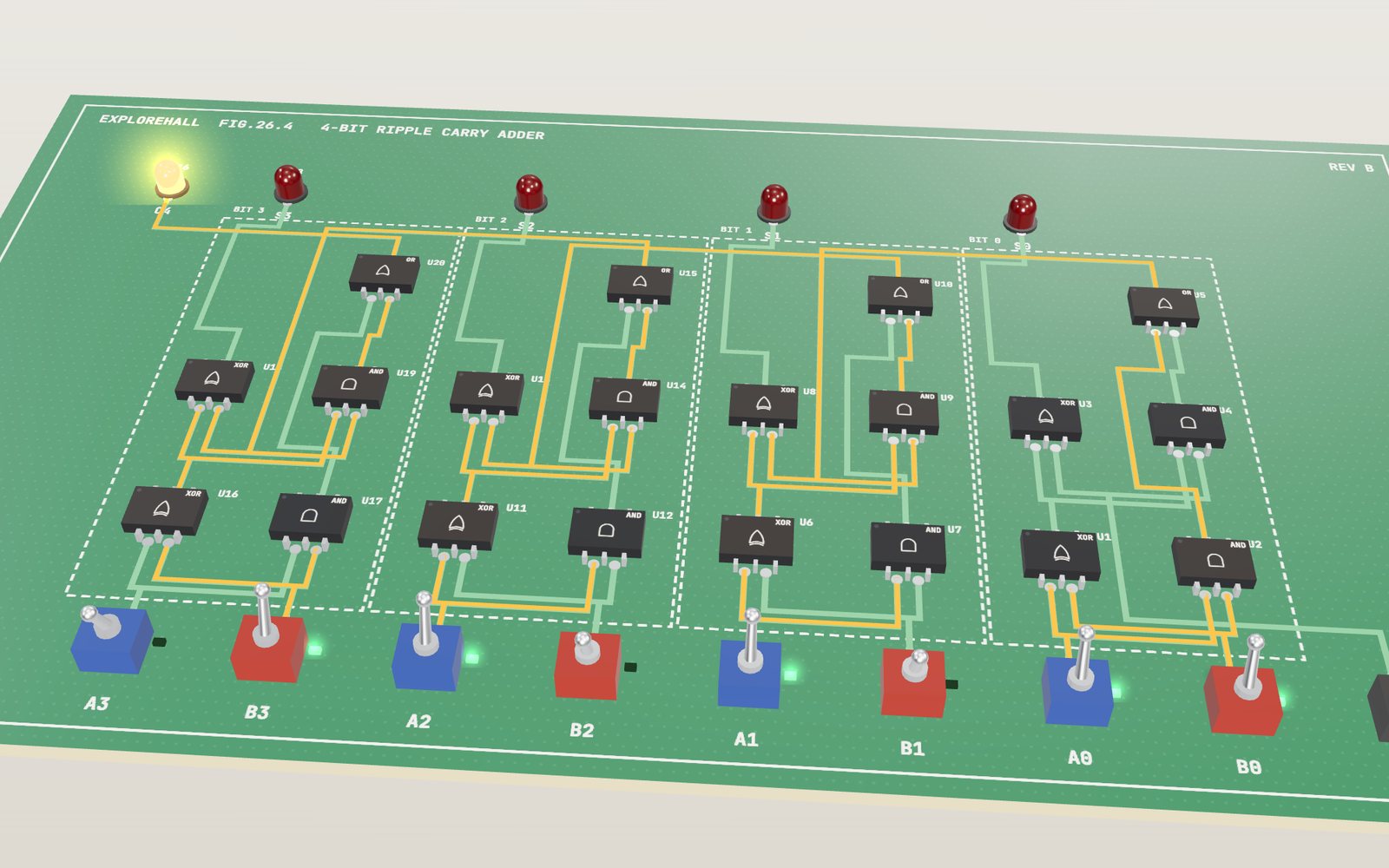
This device cannot show the 3D model. You can read the guide steps below as text.
1 / 20 Two 4-bit numbers and five LEDsThe front row holds two 4-bit numbers. Here A is 0111 (7) and B is 1001 (9). Watch the light run through 20 gates until the LEDs read 10000, which is 16. Tap any switch to change a bit, or pick another circuit with the Circuit slider.
Drag to turn. Scroll or pinch to zoom.
Adding 7 and 9 with nothing but switches
Logic gates add binary numbers by producing a sum bit and a carry bit for each column. A full adder also accepts the carry from the previous column. In a ripple carry adder, each carry must travel through the gates before the final answer settles.
On paper, 7 + 9 takes one line: 6 in the ones column, carry the 1, and the answer is 16. A computer has no paper and no idea what a number is. What it has are switches that are either on or off. So how does a pile of switches get 16 out of 7 and 9?
The board above answers that one layer at a time, and then keeps going. It opens on a 4-bit ripple carry adder: eight bit switches along the front edge for two numbers, A and B, each from 0 to 15, twenty logic gates behind them, and five LEDs along the back edge for the result. When you flip a switch, the copper traces that carry a 1 light up, and the light moves through the gates at the speed you set with the gate delay slider. The panel in the corner shows the inputs and the LEDs in binary and in decimal at the same time.
The Circuit slider swaps the board for one of 15 circuits built from the same kind of gate chip: a single gate, a half adder, a full adder, 4-bit and 8-bit ripple carry adders, a carry lookahead adder, an adder-subtractor, a comparator, a multiplexer, a 7-segment decoder, an SR latch, a D flip-flop, a counter, a small ALU and a puzzle made of four NAND gates. Every one of them runs on the same simulation, so you can compare how many gates each needs and how long each takes to settle.
Numbers written with two digits
In decimal each column is worth ten times the column to its right: ones, tens, hundreds. Binary works the same way with two instead of ten. The columns are worth 1, 2, 4 and 8, so four bits can hold any number from 0 (0000) to 15 (1111). On the board, switch A0 is the ones column and A3 is the eights column, and the small numbers printed under each switch give its value.
Seven is 4 + 2 + 1, which is 0111. Nine is 8 + 1, which is 1001. Their sum, 16, needs a fifth column worth 16, so the answer is 10000. That fifth column is the carry LED, C4. Whenever a sum is bigger than 15, the carry LED is the only way the board can show it.
Binary suits electronics because a wire only has to be in one of two clearly different states. A circuit does not have to tell 3 volts from 3.5 volts, only "high" from "low", and that is much easier to do reliably billions of times a second.
A transistor used as a switch
Set the Circuit slider to One gate and choose Wire under the model. Switch X connects an LED to the supply through a jumper, and the LED shows exactly what the switch says: 1 is on, 0 is off.
Now choose Transistor. The model shows an NPN transistor with three legs. A small current into the middle leg (the base) lets a much larger current flow between the other two (the collector and the emitter), and the LED lights. Take the base current away and the LED goes dark. The transistor has become a switch that is flipped by electricity instead of by a finger.
This is a simplification, and the model says so. A real transistor is an analogue part: more base current gives more collector current over a range. Logic circuits are designed so that the transistor only spends time fully off or fully on and passes through the middle as quickly as it can. That is what lets us treat it as a switch.
Gates made from pairs of transistors
Once a switch can control another switch, you can build decisions. Chips today use a kind of transistor called the MOSFET, in two types: n-channel transistors conduct when their input is high, p-channel transistors conduct when it is low. CMOS logic pairs them so that one network can pull the output up to the supply and the other can pull it down to ground, and for any input exactly one of the two networks conducts. A gate standing still draws almost no current. That property, shown by Chih-Tang Sah and Frank Wanlass at Fairchild in 1963, is the reason a phone can hold billions of transistors without melting.
Count the transistors and the gates stop costing the same:
| Gate | What it does | CMOS transistors |
|---|---|---|
| NOT | flips its input | 2 |
| NAND | 0 only when both inputs are 1 | 4 |
| NOR | 1 only when both inputs are 0 | 4 |
| AND | NAND followed by NOT | 6 |
| OR | NOR followed by NOT | 6 |
| XOR | 1 when the inputs differ | 12 in the plain form used here |
The surprise is that AND, the gate everyone learns first, costs more than NAND. In CMOS the natural gates are the inverting ones, because the n-channel network pulls the output down: two n-channel transistors in series pull down only when both inputs are 1, which is NAND, and two in parallel make NOR. To get AND you add an inverter. Turn on Transistors per chip and each chip on the board shows its own count; the One gate bench lets you step through all seven types and the plain wire.
NAND has one more property. With NAND gates alone you can build NOT (tie both inputs together), AND (a NAND and a NOT), OR (invert both inputs first) and everything else. The last circuit on the board is a puzzle built on this: four NAND gates whose inputs you choose in the lab under the controls. Get the wiring right and the output matches XOR in all four rows.
The half adder: XOR for the sum, AND for the carry
Look at the XOR truth table. 0 + 0 = 0, 0 + 1 = 1, 1 + 0 = 1, and 1 + 1 = 10 in binary, which is 0 in this column with a 1 carried. The right-hand digit of every answer is exactly the XOR column. The carry is 1 only in the last row, which is exactly AND.
So one XOR and one AND fed by the same two bits add them. This pair is called a half adder. On the Half adder board it stands alone; on the 4-bit adder it is the first block in every bit. With A and B both at 1, the XOR gives sum 0 and the AND gives carry 1.
The full adder: three bits in, two bits out
A half adder is enough for the ones column, but every other column has three things to add: a bit of A, a bit of B and the carry coming from the right. The full adder handles this with two half adders and an OR gate. On the board each bit uses these names:
- p = A xor B and g = A and B (the first half adder)
- S = p xor C and t = p and C (the second half adder adds the incoming carry C)
- Carry out = g or t
The OR gate never sees two 1s at once. If A and B are both 1, then p is 0 and t cannot be 1. It only joins the two ways a carry can be made: the column itself made one (g), or the column passed on the carry it received (t). The eight rows of the full adder truth table cover every case, and the largest, 1 + 1 + 1 = 3, comes out as carry 1 and sum 1.
Five gates per bit and four bits make the 20 gates of the 4-bit adder. The carry out of each full adder is wired to the carry in of the next one to the left, like the "carry the 1" step on paper. That chain is why it is called a ripple carry adder. While it runs, the truth table in the corner marks which row each bit is using, so you can watch bit 0 sit on 1 1 0 while bit 3 waits on 0 1 1.
Why the carry is slow
No gate answers instantly. When its inputs change, the output follows a short time later, called the gate delay or propagation delay. The model gives every gate a delay of exactly one unit, and the slider stretches that unit from 0.05 to 2.4 seconds so you can watch it.
Here is 7 + 9, starting from a board at 0 + 0:
| Gate delay | What changes |
|---|---|
| 1 | Every first-level XOR and AND reacts to the new switches. Bit 0 (1 + 1) makes g = 1. |
| 2 | The carry into bit 1 turns on. Bits 1, 2 and 3 show a sum of 1 for now. |
| 3 to 4 | Bit 1 adds its carry: its sum goes back to 0 and its carry out turns on. |
| 5 to 6 | The same happens in bit 2. |
| 7 to 8 | Bit 3 drops to 0 and C4 lights. The LEDs read 10000, which is 16. |
Each bit needs two gate delays to pass the carry along: one for the AND that makes t, one for the OR that makes the carry out. Across four bits the last carry lands after 8 delays. The worst case for the 4-bit board is 9 delays, which matches 2n + 1 for n = 4 bits. Turn on Delay on each chip and every chip shows the delay at which its output last changed; along the carry chain the numbers climb 2, 4, 6, 8.
Watch the LEDs during those 8 delays and you will see wrong answers. At delay 6 the panel can read 01000, which is 8. Nothing is broken: those LEDs are showing a sum computed before the carry arrived. Real circuits have the same short false outputs, called glitches, which is why a processor waits a fixed time for the slowest path before it reads an adder's output. The length of that wait is one of the things that sets the clock speed. The Timing chart shows the same thing as waveforms, with each output stepping up and down before it settles.
The 8-bit board makes the cost plain. It is the same full adder eight times, 40 gates, and 255 + 1 sends a carry through every bit: the LEDs settle after 16 gate delays, twice as long as 15 + 1 on the 4-bit board. A 64-bit ripple carry adder built the same way would need 129 gate delays in the worst case. If you want to see one delay at a time, turn on One delay at a time and press Next delay under the model.
Working out the carries ahead
Fast adders do not wait for the ripple. Look again at the full adder: a column makes a carry by itself when g = A and B is 1, and passes on the carry it receives when p = A xor B is 1. Those two signals are ready after one gate delay in every column at once. From them each carry can be written out in full:
- C1 = g0 + p0 C0
- C2 = g1 + p1 g0 + p1 p0 C0
- C3 = g2 + p2 g1 + p2 p1 g0 + p2 p1 p0 C0
- C4 = g3 + p3 g2 + p3 p2 g1 + p3 p2 p1 g0 + p3 p2 p1 p0 C0
Read C2 as a sentence: there is a carry into bit 2 if bit 1 made one, or if bit 1 passes on a carry made by bit 0, or if bits 1 and 0 both pass on the carry in. Each line is a row of AND gates followed by one OR, so every carry arrives after three gate delays, and the sums one delay later. The Carry lookahead board does this with 26 gates. Put 15 + 1 on it and it settles in 4 gate delays, where the ripple board took 8. The panel's table shows P, G and the carry for each bit.
The price is in the AND gates. C4 already needs a 5-input AND and a 5-input OR, and the terms grow with every bit, so wide adders combine the two ideas: small lookahead blocks of four bits, with a second level of lookahead between the blocks. IBM's Gerald Rosenberger filed a patent for a binary carry lookahead adder in 1957. Charles Babbage had seen the same problem a century earlier and designed a mechanism to anticipate carries for his analytical engine. Today a 4-bit adder with "fast carry" is a catalogue chip: Texas Instruments still lists the SN74LS283.
Subtracting with the same adder
Computers do not need a separate subtractor. In two's complement, the usual way to store negative numbers, minus B is written as "flip every bit of B, then add 1". So A − B is A + (not B) + 1.
The Adder-subtractor board adds one XOR per bit in front of B. With SUB off, each XOR passes its B bit straight through; with SUB on, each XOR flips its bit, and the same SUB line feeds the carry in, which supplies the extra 1. Try 5 − 7. B = 0111 becomes 1000, the adder works out 0101 + 1000 + 1 = 1110, and 1110 read as a signed 4-bit number is −2. Read as an unsigned number it is 14, which is also right in its own way: 5 − 7 + 16 = 14. The same bits mean different things depending on how you read them, and the panel shows both.
A signed 4-bit number only runs from −8 to 7, so some answers do not fit. The board's green V LED catches this: it is an XOR of the carry into the top bit and the carry out of it, and it lights when they differ. 7 + 1 (SUB off) lights it, because 0111 + 0001 = 1000, which reads as −8. The extra XOR row costs one more gate delay at the start, and the V gate one more at the end, so the worst case on this board is 11 delays.
Comparing two numbers
How does a circuit decide that 9 is bigger than 5? The way you would do it with written numbers: look at the highest digit where they differ. The Comparator board works it out per bit. A > B in one bit means A is 1 and B is 0 (an AND with an inverter on B), A < B means the opposite, and the bit is equal when neither is true, which is a NOR of the two.
Then it ranks the bits. A is bigger if bit 3 says so, or if bit 3 is equal and bit 2 says so, or if bits 3 and 2 are equal and bit 1 says so, and so on down. Those are four AND terms joined by an OR, the same shape as the lookahead carries. 1001 against 0101 differ first at bit 3, where A has the 1, and the A > B LED lights after 4 gate delays (the worst case on this board is 5). The board uses 29 gates. The TI SN74LS85 does the same job in one package and has extra inputs so that several chips can compare longer numbers.
Choosing one input and drawing a digit
Two more circuits use the same pattern of AND gates collected by an OR.
A multiplexer chooses. The 4-to-1 board has four data inputs, D0 to D3, and two select bits. Each data input goes into a 3-input AND that also takes the select bits (or their inverses), so for any setting exactly one AND is open, and the OR passes its data bit to Y. Seven gates and three gate delays. Wherever one wire has to carry one of several signals, from the register file of a processor to the source switch on a TV, there is a multiplexer.
A decoder draws. A 7-segment display has seven bar-shaped LEDs named a to g, and each digit lights a different set: 1 lights b and c, 8 lights all seven. For every segment you can list the digits that light it and simplify that list into a sum of products, a handful of AND terms joined by an OR. The board's decoder was worked out that way: 4 inverters, 28 shared AND terms and 7 ORs, 39 gates, three gate delays from switch to segment. It draws the hex digits A to F as well as 0 to 9. The TI SN74LS47 is the catalogue version for 0 to 9.
Circuits that remember
Everything so far forgets. Change the switches and the output follows; nothing depends on what happened before. Memory needs a loop.
The SR latch is two NOR gates, each feeding its output into the other. With S and R both 0 the loop holds whatever it had, Q = 1 or Q = 0, and keeps holding it as long as power stays on. A 1 on S forces Q to 1, a 1 on R forces it to 0. Set Q, turn S off again, and Q stays at 1. That is one bit of memory made of eight transistors.
The latch has a forbidden input. With S and R both 1 both outputs are 0, and if you then release both at the same moment, the two gates race. In the model, where both gates have exactly the same delay, the loop never settles: the outputs flip together every gate delay and the panel says so. A real latch is never perfectly balanced, so one side wins, but which one and how long it takes cannot be predicted. Engineers call this metastability, and digital designs are arranged so that it cannot happen in normal use.
A D flip-flop removes the problem by taking in data only at one instant. The board's version is the six-NAND design used in the 7474 chip. While the clock is low or high, D can change as often as it likes and Q does not move. Only at the moment CLK rises from 0 to 1 does Q take the value of D, and it holds it until the next rising edge. Fed 49,152 random steps of D and CLK, Q followed that rule every time.
Counting clock pulses
Put four flip-flops side by side, add a small circuit that works out the current number plus one, and feed the result back to the flip-flops' D inputs. Every clock pulse loads the next number. The 4-bit counter board does exactly that with 30 gates: 24 NANDs in the four flip-flops and six gates for the adder. Bit 0 always flips, bit 1 flips when bit 0 is 1, bit 2 when bits 1 and 0 are both 1, bit 3 when all three below it are 1.
Press Clock pulse and watch the order. The clock edge reaches all four flip-flops together, their outputs change two gate delays later, and the "plus one" gates then prepare the next number long before the next pulse. Because every bit changes on the same edge, it is called a synchronous counter, like the TI SN74LS161A. After 1111 it wraps round to 0000. Run through 40 pulses, it counted 0 to 15 and round again without a miss.
An ALU from the same parts
A processor's arithmetic logic unit is the circuit that does the actual sums. The 4-bit ALU board shows the idea in 59 gates. For each bit it works out four results side by side: A + B, A − B, A AND B and A OR B. Two op bits then choose which one reaches the outputs, through the same kind of AND and OR selection as the multiplexer. Op 00 adds, 01 subtracts (using the XOR row from the adder-subtractor), 10 is AND and 11 is OR.
All four results are computed all the time; the op bits only choose which one you see. That is how real ALUs work too, and it is why the ALU's longest path, 13 gate delays here, is longer than the adder's alone. Try 12 AND 10: 1100 and 1010 have only bit 3 in common, so the answer is 1000, which is 8.
How long is a gate delay?
The model counts delays; real parts measure them in nanoseconds. Texas Instruments gives a typical delay of 9 ns for its SN74HC00 NAND gates at 4.5 V, 9 to 10 ns for the older SN74LS00, and about 5 ns for the SN74AC00 at 5 V. A relay is a million times slower: the Omron G5V-1 data sheet allows up to 5 ms to operate.
Multiply that by the board's longest path. A 4-bit ripple carry adder needs 9 delays, so with 74HC00-style gates it settles in about 81 ns, fast enough for twelve million additions a second. Built from relays, the same adder would need 45 ms. The lab under the controls does this sum for whichever circuit is on the board. A modern processor adds 64-bit numbers billions of times a second because its gates are thousands of times faster and its adders use lookahead, not because the logic is any different.
Check every circuit yourself
Every circuit on the board was checked against its truth table for every possible input. The 4-bit adder gave A + B + C0 for all 512 combinations and settled on the right answer within 9 gate delays after each of the 262,144 possible changes from one input to another. The 8-bit adder was checked for all 131,072 sums and 400,000 random changes. The lookahead adder settled within 4 delays, the adder-subtractor within 11, the comparator within 5, the multiplexer and the decoder within 3, and the ALU within 13 after every one of its 1,048,576 changes. The memory circuits were run through sequences: the latch through set, hold and reset, the flip-flop through random clock and data, the counter through 40 pulses.
You can try a few on the board:
- 15 + 1 on the ripple adder: all four carries ripple, and the LEDs read 10000 after 8 delays.
- 15 + 1 on the lookahead adder: the same answer after 4 delays.
- 5 + 2: no column carries, and the answer 0111 (7) is ready after 2 delays.
- 5 − 7 on the adder-subtractor: 1110, which is −2.
How the model differs from a real chip
- Every gate has the same delay. In real logic an XOR is slower than a NAND, a gate driving many inputs is slower than one driving a single input, and delays change with temperature and supply voltage.
- Every wire takes 0.85 of a gate delay to cross, whatever its length. On a real board short traces are effectively instant; inside a chip long wires can be slower than the gates.
- Signals are perfectly 0 or 1. Real voltages rise and fall over a short time, and the board has no noise, heat or fan-out limits.
- One gate per chip. Real logic chips hold four NANDs or six inverters in one package, and they need power pins, decoupling capacitors and pull-up resistors that the board leaves out.
- The transistor on the bench is drawn as a single bipolar switch, while the transistor counts on the chips are for CMOS.
From Boole's algebra to relay adders
In 1854 George Boole published The Laws of Thought, an algebra in which logical statements are combined with operations much like multiplication and addition, and in which the symbols 1 and 0 play a special part. It was a book about reasoning, not machines.
The link to circuits came in 1937. Claude Shannon, a master's student at MIT, wrote the thesis A Symbolic Analysis of Relay and Switching Circuits. He showed that switches in series and in parallel follow the same rules as Boole's algebra, so a circuit can be designed and simplified with algebra instead of by trial. In the last chapter he gave several example circuits, including an adder for binary numbers. A paper from the thesis was published in the Transactions of the American Institute of Electrical Engineers in 1938, and it won the Alfred Noble Prize.
In the same year George Stibitz, a scientist at Bell Labs, built a demonstration adder from relays. He called it the Model K, after the kitchen table where he assembled it. Ten years later, in December 1947, John Bardeen and Walter Brattain made the first working transistor at Bell Labs, in a group led by William Shockley. The three shared the 1956 Nobel Prize in Physics "for their researches on semiconductors and their discovery of the transistor effect".
From relays to billions of transistors
The first large computers used whatever switches were at hand. Konrad Zuse's Z3 of 1941 used 2,300 relays; the Harvard Mark 1, finished in 1944, used 3,500, kept in step by a camshaft fifty feet long. Colossus, working at Bletchley Park from early 1944, switched with 2,500 valves, and ENIAC, announced at the University of Pennsylvania in February 1946, needed 18,000 vacuum tubes and filled a room 30 by 50 feet (about 9 by 15 metres). MIT's TX-0 of 1956 was the first general-purpose programmable computer built with transistors, each one in a plug-in "bottle" so it could be swapped like a tube.
Then the gates moved onto silicon. In 1961 Fairchild announced one of the first planar integrated circuits, a flip-flop with four transistors and five resistors. Texas Instruments' 7400 series of TTL logic chips, sold in cheap plastic packages from 1966, soon held more than half the logic market, and many of its parts, such as the SN7400 quad NAND, are still sold today. The Apollo Guidance Computer that first flew on Apollo 7 in 1968 was built mostly from one chip type holding two 3-input NOR gates, several thousand of them per computer.
In 1965 Gordon Moore predicted that the number of components on a chip would double every year, and later revised that to every two years. The Intel 4004 of 1971 put a whole 4-bit processor on one chip with 2,300 transistors (the Computer History Museum's timeline gives 2,250). Apple's M1 of 2020 holds 16 billion, about seven million times as many, and NVIDIA's Blackwell GPUs of 2024 hold 208 billion. Inside all of them the arithmetic is still done by adders, multiplexers and flip-flops like the ones on this board.
Questions
Why do computers use binary instead of decimal?
A wire only has to be in one of two states, high or low, and a transistor only has to be fully on or fully off. Telling two states apart is far more reliable than telling ten apart, and Boole's algebra describes two-state circuits exactly.
What is the difference between a half adder and a full adder?
A half adder adds two bits and gives a sum and a carry. A full adder adds three bits (two digits and an incoming carry). It is built from two half adders and an OR gate.
Why is it called a ripple carry adder?
Each full adder has to wait for the carry from the column on its right before its own carry out is final. The carry moves through the bits one after another, like a ripple across water.
How long does a 4-bit ripple carry adder take?
In this model each bit adds two gate delays to the carry. The worst case is 9 gate delays, and 7 + 9 settles after 8. With 74HC00-type gates at 9 ns each that is about 81 ns.
Why do the LEDs show wrong numbers for a moment?
Each column shows its sum as soon as its own gates react, before the carry from the right has arrived. These short wrong outputs are called glitches. A processor waits until the slowest path is finished before it uses the result.
What happens when the sum is bigger than 15?
Four sum bits can only show 0 to 15. The fifth LED, C4, holds the carry out of the top bit and is worth 16. With it, the board can show any sum up to 15 + 15 + 1 = 31.
Can the same circuit subtract?
Yes. Flip every bit of B and turn on the carry in, and the adder computes A minus B in two's complement. The Adder-subtractor board does this with one XOR per bit, and processors use the same trick so one adder handles both.
Why is NAND called a universal gate?
Any logic function can be built from NAND gates alone: NOT is a NAND with its inputs tied together, AND is a NAND followed by a NOT, and OR is a NAND of two inverted inputs. NOR has the same property. The NAND puzzle on the board asks for an XOR from four NANDs.
Why does AND need more transistors than NAND?
In CMOS the transistors that pull the output to ground are n-channel, and two of them in series pull down only when both inputs are 1. That makes the inverted function, NAND, with 4 transistors. AND needs an extra inverter, which brings it to 6.
Is a carry lookahead adder always better?
It is faster, but it needs more gates and much wider ones as the number of bits grows. The 4-bit lookahead board uses 26 gates against 20 for the ripple board. Wide adders use small lookahead blocks joined by a second level of lookahead.
What is the difference between a latch and a flip-flop?
A latch follows its inputs whenever they change (the SR latch sets and resets at once). A flip-flop changes only at a clock edge, so a whole circuit full of flip-flops moves forward in step, one clock pulse at a time.
How many transistors does the 4-bit adder on the board need?
Counted as CMOS gates, 168: eight XORs at 12, eight ANDs at 6 and four ORs at 6. The ALU board needs 418. The Intel 4004 needed about 2,300 for a whole processor.
Terms
- Bit: one binary digit, 0 or 1.
- Logic gate: a circuit whose output is a fixed function of its inputs, such as AND, OR, NOT, NAND, NOR or XOR.
- Truth table: a list of every input combination and the output it gives.
- Transistor: a semiconductor part in which a small current or voltage controls a larger current. In logic it is used as a switch.
- CMOS: logic built from pairs of n-channel and p-channel MOSFETs, which draws almost no current while it stands still.
- Half adder: an XOR and an AND that add two bits.
- Full adder: two half adders and an OR that add two bits and a carry.
- Carry: the 1 passed to the next column when a column's sum is 2 or more.
- Gate delay: the time a gate takes to change its output after its inputs change. Also called propagation delay.
- Ripple carry adder: full adders chained so that each carry feeds the next column.
- Carry lookahead: a faster method that works out the carries in parallel from the generate (g) and propagate (p) signals.
- Two's complement: the usual way to store negative numbers; minus B is every bit of B flipped, plus 1.
- Multiplexer: a circuit that passes one of several inputs to its output, chosen by select bits.
- Decoder: a circuit that turns a binary number into one signal per output, such as the seven segments of a digit.
- Latch: a loop of gates that holds one bit as long as power stays on.
- Flip-flop: a memory circuit that takes in its input only at a clock edge.
- ALU: arithmetic logic unit, the part of a processor that adds, subtracts and combines bits.
Sources
- University of Victoria, CENG 465, Ripple Carry and Carry Lookahead Adders (half and full adders, ripple carry, carry lookahead, gate delays). https://www.ece.uvic.ca/~fayez/courses/ceng465/lab_465/project1/adders.pdf (checked 17 October 2026)
- Google Patents, US 2,966,305, Gerald B. Rosenberger (IBM), Simultaneous carry adder (filed 16 August 1957). https://patents.google.com/patent/US2966305A/en (checked 17 October 2026)
- Doron Swade, Charles Babbage and Computational Method, The Rutherford Journal 3 (successive carriage in the Difference Engines, anticipating carriage in the Analytical Engine). https://www.rutherfordjournal.org/article030106.html (checked 17 October 2026)
- MIT Libraries, DSpace@MIT, Claude E. Shannon, A symbolic analysis of relay and switching circuits (S.M. thesis). https://dspace.mit.edu/handle/1721.1/11173 (checked 17 October 2026)
- Golomb, Berlekamp, Cover and others, Claude Elwood Shannon (1916–2001), Notices of the AMS 49(1), 2002 (the 1938 paper and the Alfred Noble Prize), via Stanford ISL. https://isl.stanford.edu/~cover/papers/paper117.pdf (checked 17 October 2026)
- Computer History Museum, Timeline of Computer History: 1937 (Stibitz's "Model K" relay adder, built on his kitchen table). https://www.computerhistory.org/timeline/1937/ (checked 18 October 2026)
- Project Gutenberg, George Boole, An Investigation of the Laws of Thought (1854), full text. https://www.gutenberg.org/ebooks/15114 (checked 16 October 2026)
- Computer History Museum, 1947: Invention of the Point-Contact Transistor (Bardeen and Brattain, December 1947). https://www.computerhistory.org/siliconengine/invention-of-the-point-contact-transistor/ (checked 17 October 2026)
- The Nobel Prize, The Nobel Prize in Physics 1956. https://www.nobelprize.org/prizes/physics/1956/summary/ (checked 16 October 2026)
- University of Texas at Austin, J. A. Abraham, VLSI Design lecture 3, Implementing Logic in CMOS (CMOS NAND, NOR, compound gates, transmission-gate multiplexer). https://www.cerc.utexas.edu/~jaa/vlsi/lectures/3-2.pdf (checked 18 October 2026)
- Cornell University, ECE 4740, lecture 14, Pass Transistors and Transmission Gates (AND as 6 transistors in static CMOS, XOR cost). https://cpb-us-w2.wpmucdn.com/sites.coecis.cornell.edu/dist/4/81/files/2019/06/4740_lecture14-pass-transistors.pdf (checked 18 October 2026)
- Computer History Museum, The Silicon Engine, 1963: Complementary MOS Circuit Configuration is Invented. https://www.computerhistory.org/siliconengine/complementary-mos-circuit-configuration-is-invented/ (checked 18 October 2026)
- Computer History Museum, The Silicon Engine, 1963: Standard Logic IC Families Introduced (TI 7400 series from 1966). https://www.computerhistory.org/siliconengine/standard-logic-ic-families-introduced/ (checked 18 October 2026)
- Computer History Museum, The Silicon Engine, 1960: First Planar Integrated Circuit is Fabricated (Micrologic flip-flop, March 1961). https://www.computerhistory.org/siliconengine/first-planar-integrated-circuit-is-fabricated/ (checked 18 October 2026)
- Computer History Museum, The Silicon Engine, 1965: "Moore's Law" Predicts the Future of Integrated Circuits. https://www.computerhistory.org/siliconengine/moores-law-predicts-the-future-of-integrated-circuits/ (checked 18 October 2026)
- Computer History Museum, The Silicon Engine, 1971: Microprocessor Integrates CPU Function onto a Single Chip (4004, 2,300 transistors). https://www.computerhistory.org/siliconengine/microprocessor-integrates-cpu-function-onto-a-single-chip/ (checked 18 October 2026)
- Computer History Museum, Timeline of Computer History: 1941 (Z3, 2,300 relays), 1944 (Harvard Mark 1, 3,500 relays), 1956 (TX-0), 1968 (Apollo Guidance Computer), 1971 (4004, 2,250 transistors). https://www.computerhistory.org/timeline/1944/ (checked 18 October 2026)
- The National Museum of Computing, Colossus (2,500 valves, working in February 1944). https://www.tnmoc.org/colossus (checked 18 October 2026)
- Penn Engineering, University of Pennsylvania, ENIAC (18,000 vacuum tubes, announced February 1946). https://www.seas.upenn.edu/about/history-heritage/eniac/ (checked 18 October 2026)
- Smithsonian National Air and Space Museum, Integrated Circuit, Dual 3 Input, Apollo Guidance Computer. https://airandspace.si.edu/collection-objects/integrated-circuit-dual-3-input-apollo-guidance-computer/nasm_A20170004000 (checked 18 October 2026)
- Texas Instruments, SN74HC00 data sheet (typical propagation delay 9 ns at 4.5 V). https://www.ti.com/lit/ds/symlink/sn74hc00.pdf (checked 18 October 2026)
- Texas Instruments, SN74LS00 data sheet (typical delays 9 ns and 10 ns). https://www.ti.com/lit/ds/symlink/sn74ls00.pdf (checked 18 October 2026)
- Texas Instruments, SN74AC00 data sheet (typical delays 6 ns and 4.5 ns at 5 V). https://www.ti.com/lit/ds/symlink/sn74ac00.pdf (checked 18 October 2026)
- Texas Instruments, product pages for SN74LS283, SN74LS85, SN74LS47, SN74LS161A and SN7400. https://www.ti.com/product/SN74LS283 (checked 18 October 2026)
- Omron, G5V-1 relay data sheet (operate time 5 ms maximum). https://omronfs.omron.com/en_US/ecb/products/pdf/en-g5v_1.pdf (checked 18 October 2026)
- Apple Newsroom, Apple unleashes M1 (16 billion transistors, 10 November 2020). https://www.apple.com/newsroom/2020/11/apple-unleashes-m1/ (checked 18 October 2026)
- NVIDIA Newsroom, NVIDIA Blackwell Platform Arrives to Power a New Era of Computing (208 billion transistors, 18 March 2024). https://nvidianews.nvidia.com/news/nvidia-blackwell-platform-arrives-to-power-a-new-era-of-computing (checked 18 October 2026)
- Calculations on this page: the gate models were worked through for every input of every combinational circuit and every change between two inputs (sampled for the 8-bit adder). Worst settle times: 4-bit ripple 9, 8-bit ripple 17 by path length (16 seen), lookahead 4, adder-subtractor 11, comparator 5, multiplexer 3, decoder 3, ALU 13 gate delays.
More exhibits
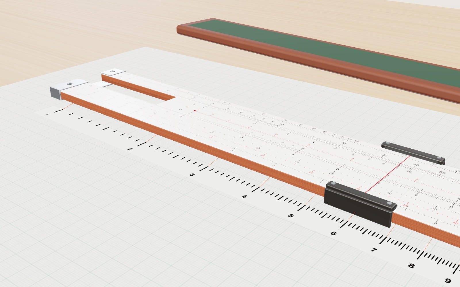
Slide rule: how to use one, with an interactive model
On a 25 cm slide rule the 2 sits 75.3 mm from the 1, because 250 × log 2 = 75.3, and laying two such lengths end to end multiplies the numbers.

How a touchscreen works: how the glass finds your finger
Under the glass of a phone lies a grid of transparent electrodes, and your finger shows up as a small dip in the charge passing between them.
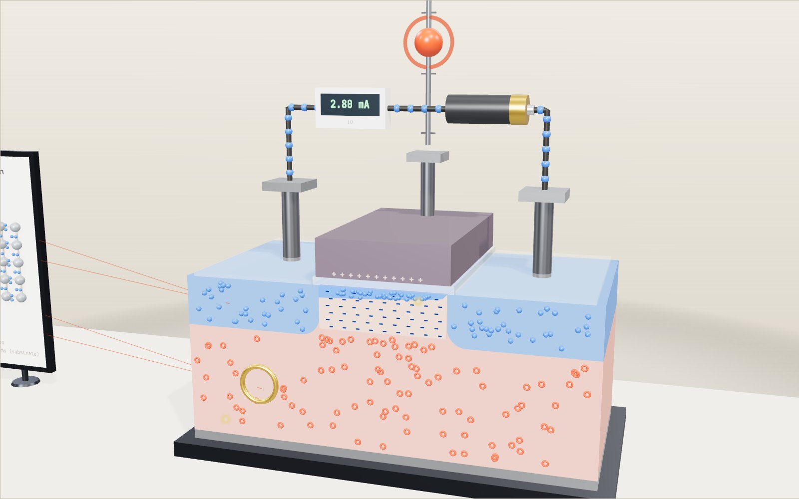
How a transistor works as a switch: the MOSFET gate
A chip with 16 billion transistors turns each one on and off with a few volts on a gate that never touches the silicon underneath.
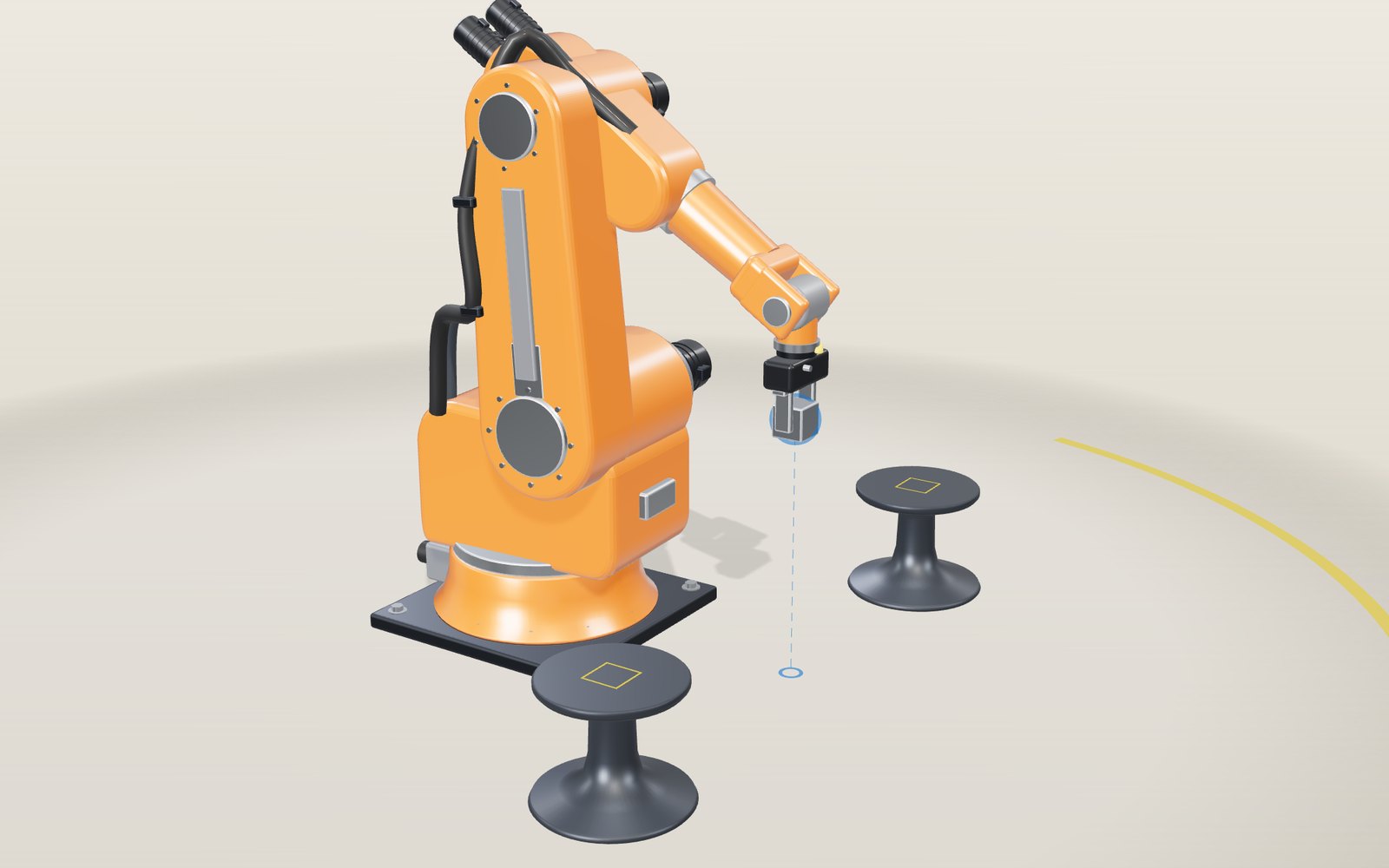
Robot arm: move the joints, how it works step by step
Slide the fingertips of a six-axis robot arm sideways at 250 mm/s past one particular line in space, and one of its wrist joints has to spin at 510° a second.
Bicycle gears: which gear makes climbing a hill easier
In a 50 by 11 gear one turn of the pedals moves a road bike 9.57 metres; in 34 by 32 it moves 2.24 metres.
How a QR code is read
Cover 30 % of a QR code with your hand and a phone still reads it. Cover one corner and it does not.