FIG. 63How It Works
Robot arm: move the joints, how it works step by step
Slide the fingertips of a six-axis robot arm sideways at 250 mm/s past one particular line in space, and one of its wrist joints has to spin at 510° a second.
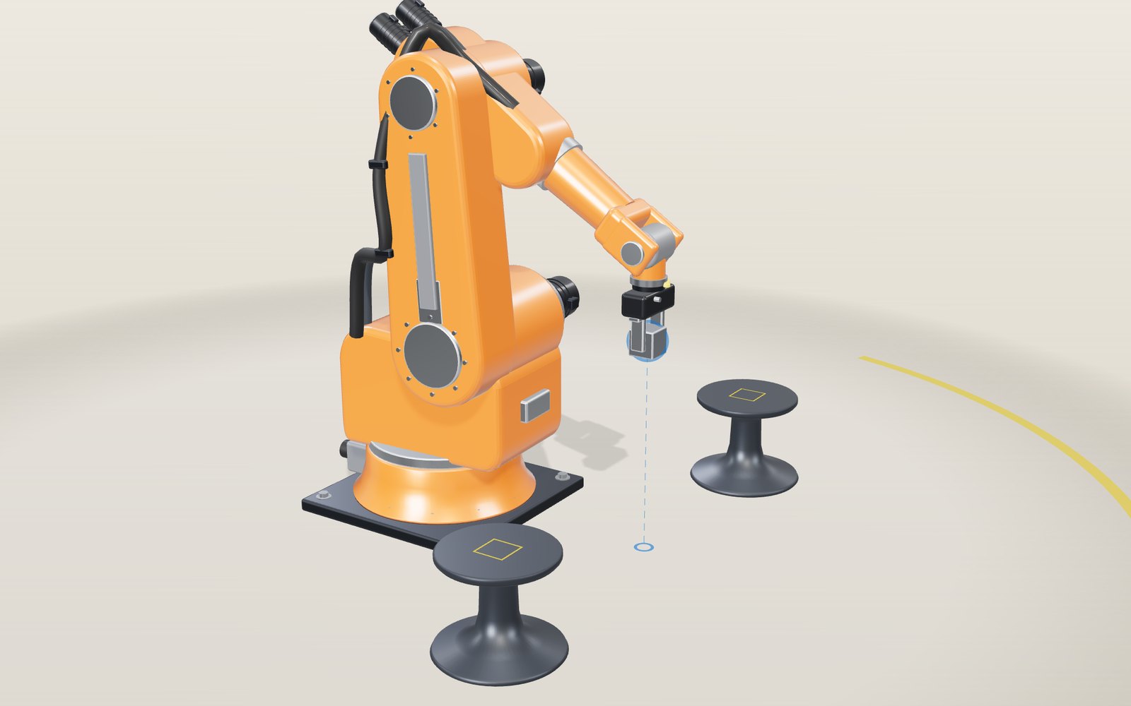
This device cannot show the 3D model. You can read the guide steps below as text.
1 / 11 A six-axis arm between two standsThe arm is bolted to the floor with a stand on each side. Six motors turn six joints, and the blue ball marks where the point between the fingers should go. At the moment it is carrying a steel block from one stand to the other.
Drag to turn. Scroll or pinch to zoom.
What the model shows
Watch a car body go down a welding line and you will see orange arms dip in, touch a seam and pull back, hundreds of times an hour. Each of those arms has to put a tool at an exact point in space, pointing in an exact direction. The motors cannot be told "go there". They can only be told an angle. This page is about the arithmetic in between.
The model is a medium-sized industrial arm with six revolute joints, bolted to the floor between two stands. The shoulder axis is 520 mm above the floor and 160 mm in front of the base axis, the upper arm is 620 mm long, the forearm 600 mm, and the tool centre point (the spot between the fingertips) is 240 mm beyond the wrist. These are model values chosen to look and behave like a typical arm of this class, not the figures of a particular product.
You can drag the blue ball and the arm will follow, or use the six joint sliders and watch the ball follow the arm. The readout in the corner shows all six angles, the position of the tip in millimetres, how fast the tip is moving and which joint is turning fastest.
Why an arm needs six joints
A rigid object in space has six independent ways to move. It can slide in three directions and turn about three axes. A gripper that has to pick a part from any position, at any angle, needs control over all six, so a general-purpose arm has six joints.
The first three joints do most of the travelling. J1 turns the whole arm about the vertical axis, J2 leans the upper arm at the shoulder and J3 tilts the forearm at the elbow. Between them they decide where the wrist goes. The last three joints sit in the wrist. J4 rolls the forearm about its own length, J5 bends the wrist and J6 rolls the flange that carries the tool. They decide which way the tool points.
In this model, as in most industrial arms, the axes of J4, J5 and J6 all pass through one point called the wrist centre. That design choice turns out to matter a great deal, as the next sections show.
From joint angles to the tip position
Going from angles to a position is called forward kinematics, and it is the easy direction. Each joint rotates everything beyond it, so you can chain the rotations together, starting at the base.
In the vertical plane of the arm, measure distances out from the J1 axis (call it r) and up from the floor (h). With J2 measured from upright and J3 measured from a level forearm, the wrist centre sits at
- r = 160 + 620 sin J2 + 600 cos(J2 + J3)
- h = 520 + 620 cos J2 − 600 sin(J2 + J3)
all in millimetres. At the starting pose J2 is 15° and J3 is 0°, which gives r = 160 + 160.5 + 579.6 = 900.0 mm and h = 520 + 598.9 − 155.3 = 963.6 mm. J5 is 75°, which adds to the 15° downward lean of the forearm to point the gripper straight down, so the tip is 240 mm lower, at 723.6 mm. J1 then swings that whole plane around the vertical axis.
The wrist joints add three more rotations on top. The model does this with ordinary 3 × 3 rotation matrices, one per joint, multiplied in order. Move any slider and the page simply runs this chain again.
Working backwards from the tip
Inverse kinematics is the other direction: given where the tip must be and which way the gripper must point, find the six angles. That is what a robot controller needs every time it plans a straight-line move, and it is much harder. The equations are non-linear, there may be several answers, and there may be none.
There are two broad ways to solve it. A numerical solver starts from the current angles, works out how a small change in each joint would move the tip (the Jacobian matrix), takes a step that reduces the error and repeats until the error is tiny. That works for almost any arm. For arms whose last three axes meet in one point, there is also a closed-form solution that needs no iteration, and the model uses that.
Splitting the problem at the wrist centre
Because the three wrist axes cross at one point, turning J4, J5 or J6 never moves that point. So the wrist centre can be found before any joint angle is known: start at the target tip and step 240 mm backwards along the direction the gripper should point.
Now the problem falls into two smaller ones.
- Position. J1 must face the wrist centre, so J1 is simply its compass bearing seen from above. In the arm's plane, the shoulder, the elbow and the wrist centre form a triangle with two known sides (620 and 600 mm) and a third side D, the measured distance from shoulder to wrist centre. The law of cosines gives the elbow angle: sin J3 = (620² + 600² − D²) ÷ (2 × 620 × 600). J2 is then the direction to the wrist centre minus the angle the elbow bend adds.
- Orientation. With J1 to J3 known, the rotation they produce is known. Whatever is left over between that and the required gripper rotation has to come from the wrist, and three wrist angles can be read straight out of that leftover rotation matrix.
Take the grasp position on the left-hand stand: tip at 620 mm out, 285 mm up and 600 mm to the side, gripper pointing down. The wrist centre is 240 mm above it, at 525 mm. Seen from above it lies 862.8 mm from the J1 axis on a bearing of 44.06°, so J1 = −44.06°. In the arm's plane r = 702.8 mm and h = 5 mm, so D = 702.8 mm. Then sin J3 = 0.3366 and J3 = 19.67°. The direction to the wrist centre is 89.59° from upright and the elbow bend accounts for 53.50°, so J2 = 36.09°. To point the gripper down, J5 must make up the rest of 90°: 90 − 36.09 − 19.67 = 34.24°.
Checking the solver both ways
Numbers like these are easy to get subtly wrong, so the page's solver was tested with the same method the browser uses. The test picks 20,000 random sets of joint angles inside the joint limits, computes the tip position and gripper rotation with forward kinematics, feeds those back into the inverse solver and runs forward kinematics again on the answer. Sets within about 1° of J5 = 0 are left out, for a reason explained below. For the remaining 19,836 the worst tip error was 7 × 10⁻¹² mm, and every set came back to its original angles to within 10⁻¹³ radian.
The browser makes the same check on every frame as you drag: the readout's tip position comes from running forward kinematics on the angles the solver chose, so if the ball and the readout ever disagree, something is wrong.
How far the arm can reach
The wrist centre can never be more than 620 + 600 = 1,220 mm from the shoulder axis, when the arm is fully stretched. With the gripper held level that puts the tip at most 1,620 mm from the J1 axis. Drag the ball beyond that and the arm stretches as far as it can toward it. The ball turns red and the readout says how many millimetres short the tip is. Ask for a point 2 m away at shoulder height and the tip stops at 1,617 mm, 386 mm short.
The reach is not a perfect shell, because the joints have limits. In the model J2 can lean 60° back and 100° forward, and J3 can go 85° up and 80° down. Turn on Show reach to see the region in the arm's plane where the fingertips can go with the gripper at its current angle. Change the gripper angle and the whole shape shifts, because the tip sits 240 mm from the wrist centre in a different direction. The ring on the floor marks the 340° that J1 can sweep.
What goes wrong when the wrist lines up
Look again at the orientation step. The wrist angles are read from a rotation that the three wrist joints have to produce. When J5 is exactly zero, the J4 and J6 axes lie on one line. Turning J4 forward and J6 back by the same amount then leaves the gripper exactly where it was, so there are endless pairs of angles that do the same job, and the solver cannot tell them apart. This is called a wrist singularity. That is also why the round-trip test leaves out angle sets very close to J5 = 0: the solver returns a different, equally valid pair, so the angles cannot be compared.
The real trouble comes near the singularity rather than at it. Step 6 of the guide holds the gripper level, pointing straight out, and slides the tip 440 mm sideways, 1,155 mm above the floor, reaching 250 mm/s at the middle of the run. That path passes 20 mm from the line where the forearm points exactly along the gripper. Far from the crossing the wrist barely moves. Close to it, J4 has to roll the J5 bend from one side to the other, and J6 has to undo the roll so the gripper does not twist. Over the whole run J4 goes from −81.2° to +81.2°, and 39.2° of that happens while the tip covers the middle 20 mm. At its fastest J4 has to turn 2.04° for every millimetre of tip travel, which at 250 mm/s means 510° per second. At 1,000 mm/s it would be about 2,040° per second, and a path 10 mm closer roughly doubles both figures.
No motor can follow that, so a real controller has to slow the tip down, stop with an error, or let the path bend away from the straight line. Robotics textbooks give two revolute joint axes lining up as a basic case of a singularity: in that pose the arm loses the ability to move the tool in some direction. The cure is planning: tilt the gripper a few degrees or move the path so the wrist never comes close.
Moving a block from one stand to the other
The pick-and-place cycle in the model has eight moves. A joint move takes the arm above the block. Then three straight-line moves follow: down to the grasp height, back up after the fingers close, and 1.2 m across to the other stand. After that it lowers again, opens the fingers and lifts clear.
Every straight-line move is planned by asking the inverse solver for the angles at each frame. The gripper's rotation stays fixed in space throughout, so as J1 swings from −44.06° to +44.06°, J6 turns by the same 88° to keep the block from spinning in the fingers.
Each move speeds up and slows down smoothly. With that profile the top speed is 1.5 times the average, so a move of length L planned for a top speed v takes 1.5 L ÷ v. At 1 m/s the 1.2 m transfer takes 1.8 seconds.
Sharing the floor with people
A conventional industrial arm works inside a fence, and opening the gate stops it. Collaborative robots, or cobots, are meant to work next to people, and the safety rules for them set numbers you can check.
ISO 10218-1, the safety standard for industrial robots, says that under reduced speed control the speed of the tool centre point shall not exceed 250 mm/s. Switch on Collaborative mode and the model caps the tip at that figure; the 1.2 m transfer now takes 7.2 seconds instead of 1.8.
ISO/TS 15066 describes four ways people and robots can share space: a safety-rated monitored stop, hand guiding, speed and separation monitoring, and power and force limiting. For power and force limiting it lists how hard a robot may press on each body region. For the hands and fingers the limit is 140 N when the hand is clamped against something (quasi-static contact), and twice that, 280 N, for a brief knock where the hand can move away (transient contact). The table lists 65 N for the face, but the same document says contact with the face, skull and forehead is not permissible at all.
The same document turns force limits into speed limits. Model the hand as a spring with a stiffness of 75 N/mm and a mass of 0.6 kg, and the robot as an effective mass equal to half its moving parts plus the payload. The highest safe speed is then v = F ÷ √(μk), where μ is the reduced mass of the two. For an arm with 30 kg of moving parts carrying 2 kg, the effective mass is 17 kg, μ is 0.58 kg and the transient limit for the hand works out at 1.34 m/s. A heavier arm or payload brings that down, which is one reason cobots are light. These are example figures for this model; the standard requires a risk assessment with the real robot's values.
Where the model is simpler than a real arm
- The joints move exactly where they are told. Real joints have reduction gearboxes, often strain wave gears, with a little backlash and elasticity, and real links bend under load.
- There is no dynamics. A real controller also has to limit acceleration, torque and motor current, and slows down near singularities and joint limits.
- The solver always picks the answer nearest the current angles. The geometry allows up to eight answers for one tip pose: J1 facing the point or turned away from it, the elbow up or down, and the wrist flipped or not. The model only uses the elbow-up family.
- Collisions between the arm, the stands and the floor are not checked, apart from keeping the target above the floor.
- The cobot mode only caps speed. It does not measure contact force.
A short history
George Devol filed his patent for a programmable transfer arm in 1954, and it was granted in 1961. The machine built from it, Unimate, went to work on a General Motors line in Ewing Township, New Jersey, in 1961. In 1969 Victor Scheinman at Stanford University designed the Stanford arm, an all-electric arm with six degrees of freedom whose links were laid out so the arm solutions were quick to compute. In 1973 KUKA built its first robot, FAMULUS, and ASEA introduced the IRB 6, the first fully electric, microprocessor-controlled industrial robot; the first one went to Magnussons in Genarp, Sweden, to wax and polish steel tubes bent at 90°. Cobots came later: J. Edward Colgate and Michael Peshkin of Northwestern University invented them in 1996.
A two-joint example with two answers
The six-axis solver is easier to follow if you first do the same job with two joints. Take a flat arm with a 620 mm upper link and a 600 mm forearm, the lengths of the model, and put its shoulder at the origin. The angles here are the ordinary planar ones, so they are not the same numbers as the J2 and J3 sliders: the shoulder angle is measured from the horizontal, and the elbow angle is how far the forearm bends away from the straight line of the upper link.
Say the wrist must reach a point 800 mm out and 300 mm up. Its distance from the shoulder is D = √(800² + 300²) = 854.4 mm. The law of cosines gives the elbow bend:
- cos(elbow) = (D² − 620² − 600²) ÷ (2 × 620 × 600) = (730,000 − 384,400 − 360,000) ÷ 744,000 = −0.01935
so the elbow bends by 91.11°. A cosine does not say whether the angle is positive or negative, and that is the whole reason for two answers. With a bend of −91.11° (elbow up) the shoulder angle is 65.15° and the elbow sits at (260, 563) mm, above the line from shoulder to wrist. With +91.11° (elbow down) the shoulder angle is −24.04° and the elbow sits at (566, −253) mm, below it. Put either set of angles back into the forward equations and you get exactly (800, 300). Both arms are real, both are valid, and a controller has to pick one. The six-axis arm adds two more sources of doubling, J1 facing away and the wrist flipped, which is how one tool pose can have up to eight solutions.
Which one to pick is a practical matter. The elbow-down answer here would put the elbow 253 mm below the shoulder, which on a floor-mounted arm may mean hitting the base or the table. Controllers usually choose the solution closest to the current angles, so the arm does not suddenly swing its elbow through the other side in the middle of a move. The model does the same, and that is why you never see it flip.
How much torque each joint needs
The joints do not all work equally hard. Gravity pulls on every link, and the pull on a joint is the weight times the horizontal distance from that joint to the weight. The shoulder carries everything beyond it, at the longest distances.
Here is a rough estimate with assumed masses, since the model has none. Say the upper arm is 20 kg with its centre 310 mm from the shoulder, the forearm with its wrist motors is 12 kg with its centre 300 mm beyond the elbow, and the gripper holds a 6 kg block at the stretched-out reach of 1.22 m. With the whole arm held horizontal:
- Upper arm: 20 × 9.81 × 0.31 = 61 N·m
- Forearm: 12 × 9.81 × 0.92 = 108 N·m
- Load: 6 × 9.81 × 1.22 = 72 N·m
- Shoulder total: about 241 N·m
The elbow has to support only what lies beyond it: 12 × 9.81 × 0.30 + 6 × 9.81 × 0.60 = 71 N·m. The wrist carries far less, which is why wrist motors are small and sit back on the forearm. This also shows why the shoulder is the biggest motor on the arm, and why the same arm lifts much less when stretched out than when the load is held close to the base. At a quarter of the distance, the same block would cost the shoulder a quarter of the torque.
A servo motor cannot produce 241 N·m directly. Divide by the gearbox ratio and its efficiency. With a ratio of 120 and an assumed efficiency of 80 percent, the motor needs 241 ÷ (120 × 0.8) = 2.5 N·m, about what a motor of a few hundred watts can deliver. The cost is speed: a motor turning at 3,000 rpm moves the joint at 25 rpm, or 150° per second.
Why the motors need a reducer
That ratio is why almost every joint on a real arm has a reduction gearbox next to the motor. A motor is light and fast but weak. A gearbox trades speed for torque, and in a robot it also has to be stiff, have almost no play and fit in a joint. Two designs dominate.
A strain wave gear, sold under the name Harmonic Drive, has three parts: an elliptical wave generator on the motor shaft, a thin flexible steel cup with outside teeth (the flexspline), and a rigid ring with inside teeth (the circular spline). The circular spline has two more teeth than the flexspline. As the ellipse turns, the flexspline's teeth engage the ring at two opposite regions, and every half turn of the input moves the flexspline back by one tooth. A flexspline with 200 teeth therefore gives a ratio of 200 ÷ 2 = 100 from one stage (this tooth count is an example). The maker says the gear has zero backlash because the teeth stay engaged, and that its size and weight do not depend on the ratio.
A cycloidal gear, sold by Nabtesco as the RV reducer, uses two stages. A spur gear stage first slows the motor down, then crankshafts move two lobed discs around a ring of pins. The discs have one lobe fewer than there are pins, so each turn of the crankshaft advances the output by one pin. Ratios run from about 30:1 to over 300:1, backlash is under 1 arc minute, and the housing contains large bearings that carry the load of the arm. Nabtesco says its cycloidal gearbox can absorb up to five times its rated torque in an emergency stop. The RV design reached the market in 1985.
Strain wave gears are light and compact, and cycloidal gears carry large loads and shocks, so designers tend to weigh those traits joint by joint. Neither type is free of elasticity, and a joint with a 100:1 gear winds up slightly under load, which is one reason a real arm's tip is a little off from the computed one.
Real robots and real numbers
The first industrial robot arm worked in a die-casting plant. In 1961 a Unimate designed from George Devol's patent was installed at a General Motors plant in the Trenton, New Jersey area, where it unloaded castings from a die-casting press, a hot and dangerous job. The Henry Ford museum keeps that first machine. IEEE Spectrum reports that the prototype weighed about 1,360 kg and had to invent its own control and memory system.
More than 60 years later, arms are common. The International Federation of Robotics counted 542,000 industrial robots installed worldwide in 2024, and 4,664,000 in operation. China installed 295,000 of them, 54 percent of the world total. Japan installed 44,500 and the Republic of Korea 30,600, the fourth largest market by annual installations. Behind these numbers sit arms that look like this model: six joints, a spherical wrist and a reduction gear in each axis.
Safety rules developed alongside. ISO 10218-1 sets the 250 mm/s limit under reduced speed control used by the Collaborative mode, and ISO/TS 15066 describes four collaborative methods with body-region force limits. Its content has been folded into the 2025 edition of ISO 10218-2, according to a German robot integrator. The 280 N figure for a brief knock to the hand and the 140 N figure for a clamped hand are limits for contact. They are not the force a robot can exert in general, which depends on its payload and speed.
Medical robots use the same kinematics for a different job. The US Food and Drug Administration describes robotically-assisted surgical devices as a surgeon's console linked to a cart with three or four hinged arms that hold the camera and instruments, and notes that the device is not actually a robot because it cannot operate without direct human control. The agency has cleared such devices for procedures such as gall bladder removal and hysterectomy, and has not authorized any of them specifically for treating or preventing cancer.
Writing an arm down as a DH table
Forward kinematics needs a description of the arm: where each joint axis sits relative to the one before it. Robot makers use a compact convention named after Jacques Denavit and Richard Hartenberg. Each joint gets one row of four numbers. d is the distance along the previous joint axis, a is the length of the common perpendicular to the next axis, α is the twist between the two axes, and θ is the joint angle itself. Six rows describe a six-axis arm, and multiplying the six small transforms gives the pose of the tool.
The arm on this page can be written that way. Its first row is d = 520 mm and a = 160 mm with a twist of 90°, which places the shoulder axis above and in front of J1. The second row is a = 620 mm, the upper arm, with θ = J2 minus 90° because the model counts J2 from upright. The fourth row is d = 600 mm, the forearm to the wrist centre, and the last row is d = 240 mm, the wrist centre to the point between the fingertips. The table in the Controls tab lists all six rows. A check run with 5,000 random poses found that the DH product and the direct formula on this page agree to better than a millionth of a millimetre.
Universal Robots publishes the same kind of table for its arms, together with the mass and centre of mass of every link. For the UR5e, which shares its table with the UR7e, the rows give d1 = 162.5 mm, a2 = −425 mm, a3 = −392.2 mm, d4 = 133.3 mm, d5 = 99.7 mm and d6 = 99.6 mm. With every joint at zero the flange therefore sits at x = −425 − 392.2 = −817.2 mm, y = −(133.3 + 99.6) = −232.9 mm and z = 162.5 − 99.7 = 62.8 mm, which the check reproduces exactly. The offsets d4 and d5 are why a UR arm has its characteristic stepped wrist: its three wrist axes do not meet in one point.
That one detail changes how the arm is solved. Without a spherical wrist, the position and orientation problems no longer separate at a wrist centre. The see-through arm on the stage is solved numerically instead: start from the last answer, compute how the flange moves for a tiny change of each joint (the Jacobian), and step the joints to shrink the error, with a little damping so the steps stay small near a singularity. Run 60 times on random poses for each of the eight tables, the solver lands within 0.04 mm of the target.
Three ways to lose a direction
A singularity is a pose where the Jacobian loses rank: some direction of tool motion would need infinite joint speed. For an arm like this one, with a spherical wrist, the determinant of the Jacobian factors neatly. It equals L2 × L3 × |cos J3| × r × |sin J5|, where L2 and L3 are the 620 mm and 600 mm links and r is the horizontal distance of the wrist centre from the J1 axis. The check compares this formula with the numerical determinant on 2,000 random poses and finds them equal.
Each factor is one kind of singularity. When sin J5 is zero, J4 and J6 line up: the wrist singularity this exhibit started with. When cos J3 is zero, the upper arm and forearm lie in one line, either stretched out or folded back: the elbow singularity, at the edge of the reach area. When r is zero, the wrist centre is directly above J1: the shoulder singularity, where turning J1 spins the wrist in place instead of moving it sideways.
The Manipulability bar in the readout shows this determinant as a share of its largest value inside the joint limits. Singularity map colours the reach area by the position factors, |cos J3| × r, so the pale bands are the places to avoid when planning a fast straight move. Universal Robots arms have the same three kinds of singularity, although their wrist offsets move them slightly.
Joint moves and straight moves
A robot program can ask for a move in two ways. A joint move turns every joint from its start angle to its end angle together, each at its own even pace. A straight move keeps the tool on a straight line and solves the inverse kinematics all the way. Both start and stop at the same poses, so the difference is the path between them.
Between the two stands, a straight move covers 1.200 m in 1.80 seconds at 1,000 mm/s. A joint move between the same poses only turns J1 and J6, so the tip swings along an arc of radius 863 mm around the J1 axis. That arc is 1.327 m long and takes 1.99 seconds, but the arm never comes near a singularity. The traces on the stage show both paths.
Past the wrist singularity the difference is dramatic. The straight move slides the tip 440 mm at up to 250 mm/s while J4 peaks at 510° per second. The joint move between the same two poses takes a path only 5 mm longer and J4 never exceeds 10° per second. Real controllers offer both moves for this reason. Joint moves are faster and safer when the path in between does not matter, and straight moves are used where the tool has to follow a line, such as a weld seam or a gluing bead, after the programmer has checked the path for singularities.
Payload and joint torque on a real cobot
The torque panel uses the same principle as the estimate above: the torque about a joint is the rate at which potential energy changes when that joint turns. For the model arm it uses the assumed masses from the estimate, upper arm 20 kg and forearm 12 kg, and reproduces the 241 N·m at the shoulder and 71 N·m at the elbow for the arm held horizontal with 6 kg in the gripper.
For the Universal Robots arms it uses the link masses and centres of mass from the maker's table. Held straight out (every joint at zero except the wrist joint J4 at −90°), with its rated 7.5 kg at the flange, a UR7e needs about 129 N·m at the shoulder and 56 N·m at the elbow. A UR20, with 20 kg and a 1,750 mm reach, needs about 657 N·m at the shoulder. Those numbers show why rated payload and reach trade against each other: the UR16e carries 16 kg at only 900 mm, and the UR30 carries 30 kg at 1,300 mm. The figures here are static. A real controller adds the torque needed to accelerate the links, so the motors need more than this at full speed.
Choosing a gripper
The tool on the flange matters as much as the arm. A two finger gripper squeezes a part from its sides, so it suits parts with parallel faces and can hold them firmly against sideways forces. Robotiq lists its 2F-85 with an 85 mm stroke and a 5 kg payload, and the wider 2F-140 with a 140 mm stroke and 2.5 kg, each weighing about 1 kg. A suction cup holds a part by its top face through a vacuum, which suits boxes, sheet metal and glass but needs a flat, sealed surface. An electromagnet holds steel parts by their top face and lets go when the current stops. In the model the cup and the magnet hold the 70 mm block by its top, so the tool centre point sits 35 mm higher than with the fingers, and the pick and place cycle adjusts its heights for that.
The numbers in the robot list
Each entry in the robot list comes from the maker's product page or a space agency page, checked on 27 October 2026, and the source link sits under each entry. Payload is the rated payload, and reach is the maker's figure, which for most arms is the distance from the J1 axis to the wrist or flange at full stretch. Yaskawa gives separate horizontal and vertical reach, and the list uses the horizontal one. Space arms are listed with what their agencies give: Canadarm2 is 17 m long and can handle loads of up to 116,000 kg in orbit, the European Robotic Arm is 11 m long with seven joints and moves payloads of 8 t, and the arm on the Perseverance rover is 2.1 m long with five degrees of freedom. Values a source does not state are left out rather than estimated.
Common misunderstandings
"The arm sees where its hand is." In this model and in most industrial arms, the controller does not look at the tool. It reads each joint's encoder, runs forward kinematics and assumes the links are the length it was told. If a link bends or a gear winds up, the real tip differs from the computed one. That is why cameras and calibration are added when accuracy matters.
"Moving from A to B means moving in a straight line." Only if the controller plans it that way. A joint move turns every joint evenly from start to end, and the tip sweeps along a curve. A straight-line move needs the inverse solver at every frame, which is what the model does for the three straight-line moves in the pick-and-place cycle, and it is the kind of move that can run into a singularity.
"More joints always means more skill." Six are enough to place and aim a tool. A seventh joint adds redundancy, so the same tool pose can be reached with different elbow positions, and that helps avoid obstacles. It also means the solver has infinitely many answers instead of a handful, so it must be told how to choose.
"A cobot is safe by itself." The standards judge a whole application. A gentle arm holding a sharp knife is not safe, and speed limits that are fine for a hand may not be fine for the head. ISO/TS 15066 requires a risk assessment with the real robot, tool and payload; the figures in this exhibit are examples.
"250 mm/s is the cobot speed limit." It is the limit for reduced speed control in ISO 10218-1. In power and force limiting, the allowed speed comes from the force limit and the effective mass, as in the 1.34 m/s example above, and can be much higher.
Things to try on the screen
- Tap Part names, then drag the blue ball slowly in a circle around the arm. Watch the J1 reading follow the ball's bearing from above, and see which joint readouts change when the ball moves closer to the base.
- Turn on Show reach and move the Gripper angle slider from 0 to 90. The blue region shifts, because the tip hangs 240 mm from the wrist centre in a new direction. Find the angle where the arm can reach highest.
- Drag the ball farther than the arm can stretch. It turns red, and the readout says how far short the tip is. About 1.6 m at the level gripper is the limit.
- Set J5 to 0. The J4 and J6 axes now lie along one line, so turn J4 one way and J6 back by the same amount: the gripper stays where it was. That is the wrist singularity from the section above, seen directly.
- Start Play, then switch on Collaborative mode, and time one transfer. It takes 7.2 seconds instead of 1.8.
- Try the six joint sliders without touching the ball, and write down the J2 and J3 pair that puts the tip on the floor between the stands. Then check it by dragging the ball there.
- Open the DH bench in the Controls tab, pick UR3e, and drag the ball out to a stand. The see-through arm stops short and the panel says by how many millimetres, because its reach is 500 mm.
- Turn on Singularity map, then drag the ball across a pale band and watch the Manipulability bar fall toward zero.
Questions
What does six-axis mean?
It means six joints in a chain, each turning about its own axis. Six is the number needed to place a tool at any position and point it in any direction within reach, because a rigid object can slide three ways and turn three ways.
Why does a robot need inverse kinematics if its motors only take angles?
Jobs are described by where the tool must be, such as a weld seam, a part on a conveyor or a screw hole. Something has to turn each of those points into six angles. For straight-line moves the controller does that many times along the path, not only at the ends.
Is there only one set of angles for each position?
Usually not. For an arm like this one a single tip pose can be reached in up to eight ways, by turning J1 to face the point or away from it, bending the elbow up or down, and flipping the wrist. The model picks the answer closest to the current angles so the arm never jumps.
What exactly is a singularity?
It is a pose where two or more joint axes line up, so the arm loses the ability to move the tool in some direction, or several joint combinations do the same thing. Near one, a small, slow tool move can demand a very fast joint move. In the model a path 20 mm from the wrist singularity asks J4 for 510° per second at a tip speed of 250 mm/s.
Why does the ball turn red?
It turns red when the solver cannot reach the point exactly, either because it is further away than the stretched arm or because a joint would have to pass its limit. The arm then goes as close as it can and the readout says how far off it is or which joint is at its limit.
How do collaborative robots avoid hurting people?
They combine several measures from the standards: limiting the tool speed, monitoring the distance to people and slowing down as they approach, stopping when someone enters a zone, and limiting the force they can press with. ISO/TS 15066 lists force limits by body region, for example 140 N for a clamped hand.
Does a real controller solve the equations the same way?
For arms whose three wrist axes meet in one point, closed-form solutions like the one here are common because they are fast and predictable. Arms without that layout, or with seven joints, usually rely on numerical methods that use the Jacobian and iterate toward the answer.
Can the arm reach behind itself?
Partly. J1 can turn 170° either way, which leaves a 20° gap behind the base, and the upper arm can lean back 60°. The solver also considers J1 facing away from the point with the upper arm leaning back over the base, and uses that answer only when it fits the limits and is closer to the current pose.
Why does a reaching problem have two answers for an elbow arm?
The law of cosines gives the cosine of the elbow angle, and a cosine is the same for a positive and a negative angle. The two angles put the elbow above or below the line from shoulder to wrist. In the example with a wrist at 800 mm out and 300 mm up, the elbow-up pose has the shoulder at 65.15° and the elbow-down pose at −24.04°, and both reach the point exactly.
Why do robot joints need a reduction gearbox?
A motor is fast and light but weak. In the torque estimate above, the shoulder needs about 241 N·m, while a motor behind a 120:1 gearbox at 80 percent efficiency needs only about 2.5 N·m. The price is speed, since 3,000 rpm at the motor becomes 25 rpm at the joint.
What is the difference between a strain wave gear and a cycloidal gear?
A strain wave gear deforms a thin steel cup against a ring with two more teeth, and gets its ratio from the tooth count, for example 200 ÷ 2 = 100. A cycloidal gear uses a spur stage followed by lobed discs rolling around pins, and the ratio comes from both stages. Both have very little backlash.
Is a surgical robot really a robot?
The US FDA says that a robotically-assisted surgical device is not actually a robot, because it cannot perform surgery without direct human control. The surgeon moves controls at a console, and the arms on a bedside cart move the instruments.
What are DH parameters?
Four numbers per joint, named after Denavit and Hartenberg, that say how each joint axis sits relative to the one before: a distance along the old axis (d), a distance across to the new axis (a), a twist (α) and the joint angle (θ). Six rows describe a six-axis arm. Universal Robots publishes its tables, and the Controls tab shows them.
Why does a UR arm need a numerical solver when this arm has a formula?
The three wrist axes of a UR arm do not meet in one point because of the d4 and d5 offsets, so the problem does not split at a wrist centre. Closed-form solutions for that layout exist, but a damped Jacobian solver is simpler to show and lands within 0.04 mm in the check.
Is a joint move or a straight move faster?
Usually the joint move, because each joint takes its shortest turn. Between the two stands the joint move takes 1.99 seconds along a 1.327 m arc and the straight move 1.80 seconds along 1.200 m at the same tip speed limit, but past the wrist singularity the straight move needs J4 to reach 510° per second.
Terms
- Joint (axis): one rotating connection in the arm. J1 is nearest the floor and J6 is nearest the tool.
- Forward kinematics: working out where the tool is from the joint angles.
- Inverse kinematics: working out the joint angles that put the tool at a given position and orientation.
- Tool centre point (TCP): the reference point on the tool that the controller positions, here the point between the fingertips.
- Wrist centre: the point where the axes of J4, J5 and J6 cross.
- Spherical wrist: a wrist whose three axes meet in one point, which allows a closed-form inverse solution.
- Jacobian: the matrix that says how fast the tool moves for small changes of each joint angle.
- Singularity: a pose where joint axes line up and the arm loses a direction of motion; the wrist case is also called a wrist flip.
- Workspace: the set of points the tool can reach.
- Cobot: a robot designed to work in direct, close contact with people.
- Power and force limiting: a collaborative method in which contact may happen, but force and pressure stay below set limits.
- Quasi-static and transient contact: a body part clamped against something, versus a brief knock where it can move away.
- Backlash: the small play between gear teeth, which lets the output move a little before the input moves it.
- Reduction ratio: how many turns of the motor give one turn of the joint, for example 120:1.
- Elbow up / elbow down: the two ways a two-link arm can reach the same point.
- DH parameters: four numbers per joint (d, a, α, θ) that describe the geometry of a serial arm.
- Manipulability: the size of the Jacobian's determinant, which falls to zero at a singularity.
- Joint move and straight move: interpolating the joint angles, or keeping the tool on a straight line.
- Rated payload: the largest load the maker allows at the flange, usually with conditions on the centre of mass.
Sources
- International Federation of Robotics, Robot History (KUKA Famulus 1973, first robot with six electromechanically driven axes; ASEA IRB 6 shown in August 1973, first fully electric microprocessor-controlled robot 1974, bought by Magnussons in Genarp to wax and polish steel tubes bent at 90°; Scheinman's Vicarm). https://ifr.org/robot-history (checked 17 October 2026)
- IEEE Spectrum, ROBOTS: Unimate (Devol's 1954 patent filing; first Unimate at a General Motors plant in Ewing Township, New Jersey, in 1961). https://robots.ieee.org/robots/unimate/ (checked 17 October 2026)
- George C. Devol, Programmed article transfer, US Patent 2,988,237, filed 1954, published 13 June 1961, Google Patents. https://patents.google.com/patent/US2988237A/en (checked 17 October 2026)
- Stanford University Computer Science, display text The Stanford Arm (designed in 1969 by Victor Scheinman at SAIL; six-degree-of-freedom all-electric arm; links laid out to simplify the arm solutions). http://infolab.stanford.edu/pub/voy/museum/pictures/display/1-Robot.htm (checked 17 October 2026)
- Kevin M. Lynch and Frank C. Park, Modern Robotics: Mechanics, Planning, and Control, Cambridge University Press 2017, preprint from Northwestern University (chapter 4 forward kinematics, 6.1 analytic inverse kinematics for six-joint arms, 6.2 numerical inverse kinematics with the Jacobian, 5.3 singularities including two collinear revolute joint axes, harmonic drive gearing in robot joints). http://hades.mech.northwestern.edu/images/7/7f/MR.pdf (checked 17 October 2026)
- Michael Peshkin, Northwestern University, Cobots: Robots for collaboration with people (invented by J. Edward Colgate and Michael Peshkin in 1996). http://peshkin.mech.northwestern.edu/cobot (checked 17 October 2026)
- ISO 10218-1:2011 preview, iTeh Standards (5.6.2: under reduced speed control the TCP speed shall not exceed 250 mm/s; 3.19.2 safety-rated reduced speed). https://standards.iteh.ai/catalog/standards/iso/514dc52b-e620-4f18-bbae-b8cbccb118cd/iso-10218-1-2011 (checked 16 October 2026)
- IBF Solutions, New standards for industrial robots EN ISO 10218-1 and -2 (reduced speed no greater than 250 mm/s; ISO/TS 15066 content incorporated into ISO 10218-2:2025). https://www.ibf-solutions.com/en/seminars-and-news/news/new-standards-for-industrial-robots-en-iso-10218-1-and-2 (checked 16 October 2026)
- ISO/TS 15066:2016, Robots and robotic devices: Collaborative robots, copy hosted for a Sapienza University of Rome course (5.5.1 the four collaborative methods; Table A.2 biomechanical limits, hands and fingers 140 N quasi-static, transient multiplier 2, face 65 N; contact with face, skull and forehead not permissible; Table A.3 hands 75 N/mm and 0.6 kg; formulas A.2 to A.6). https://www.diag.uniroma1.it/deluca/pHRI_elective/ISO_TS_15066_2016_en.pdf (checked 16 October 2026)
- International Federation of Robotics, press release Global Robot Demand in Factories Doubles Over 10 Years (25 September 2025; World Robotics 2025: 542,000 installed in 2024, 4,664,000 in operation, China 295,000 and 54 percent, Japan 44,500, Republic of Korea 30,600). https://ifr.org/ifr-press-releases/news/global-robot-demand-in-factories-doubles-over-10-years (checked 22 October 2026)
- Harmonic Drive LLC, Strain wave gear technology (wave generator, flexspline and circular spline; circular spline has two more teeth; zero backlash; size and weight independent of ratio). https://www.harmonicdrive.net/technology (checked 22 October 2026)
- Nabtesco Motion Control, Engineering: two stage cycloidal design (RV reducer, backlash under 1 arc minute, integrated bearings, emergency stop capacity of five times rated torque). https://www.nabtescoprecision.com/engineering (checked 22 October 2026)
- Nabtesco, Functional principle of cycloidal gears (two reduction stages, ratios 30:1 to over 300:1, RV gearbox on the market in 1985). https://www.nabtesco.de/en/service/faq/technologies/functional-principle-of-cycloidal-gears (checked 22 October 2026)
- US Food and Drug Administration, Computer-Assisted Surgical Systems (console, bedside cart with three or four hinged arms, not actually a robot, cleared procedures, no authorization for cancer treatment). https://www.fda.gov/medical-devices/surgery-devices/computer-assisted-surgical-systems (checked 22 October 2026)
- The Henry Ford, Robot, First Unimate Robot Ever Installed on an Assembly Line, 1961 (installed at the General Motors plant in Trenton, New Jersey, in 1961 to unload a die-casting press). https://www.thehenryford.org/collections/explore/artifact/183434 (checked 22 October 2026)
- Allison Marsh, In 1961, the First Robot Arm Punched In, IEEE Spectrum, 30 August 2022 (Unimate prototype about 1,360 kg; had to invent its own programming controls and memory). https://spectrum.ieee.org/unimation-robot (checked 22 October 2026)
- Universal Robots, DH Parameters for calculations of kinematics and dynamics (a, d and α for UR3e, UR5e/UR7e, UR10e/UR12e, UR15, UR16e, UR18, UR20, UR30, link masses and centres of mass). https://www.universal-robots.com/articles/ur/application-installation/dh-parameters-for-calculations-of-kinematics-and-dynamics/ (checked 27 October 2026)
- Universal Robots, UR3e product page (3 kg, 500 mm, 11.2 kg, ±0.03 mm). https://www.universal-robots.com/products/ur3e-cb5/ (checked 27 October 2026)
- Universal Robots, UR7e product page (7.5 kg, 850 mm, 20.6 kg). https://www.universal-robots.com/products/ur7e-cb5/ (checked 27 October 2026)
- Universal Robots, UR12e product page (12.5 kg, 1,300 mm, 33.5 kg). https://www.universal-robots.com/products/ur12e-1300/ (checked 27 October 2026)
- Universal Robots, UR15, UR16e and UR18 product pages (15 kg and 1,300 mm; 16 kg and 900 mm; 18 kg and 950 mm). https://www.universal-robots.com/products/ur16e-cb5/ (checked 27 October 2026)
- Universal Robots, UR20 product page (20 kg, 25 kg extended, 1,750 mm, 64 kg). https://www.universal-robots.com/products/ur20-1750/ (checked 27 October 2026)
- Universal Robots, UR30 product page (30 kg, 35 kg extended, 1,300 mm, 63.5 kg). https://www.universal-robots.com/products/ur30-1300/ (checked 27 October 2026)
- KUKA, KR AGILUS (KR 6 R700-2: 6 kg, 726 mm; KR 6 R900-2: 6 kg, 901 mm). https://www.kuka.com/en-de/products/robotics-systems/industrial-robots/kr-agilus (checked 27 October 2026)
- KUKA, KR 1000 titan (1,000 kg at 3,202 mm; L750 version 750 kg at 3,601 mm). https://www.kuka.com/en-de/products/robotics-systems/industrial-robots/kr-1000-titan (checked 27 October 2026)
- KUKA, LBR iiwa (7 axes; 7 kg at 800 mm and 14 kg at 820 mm; joint torque sensors). https://www.kuka.com/en-de/products/robotics-systems/industrial-robots/lbr-iiwa (checked 27 October 2026)
- FANUC America, CRX-10iA (10 kg, 1,249 mm, 6 axes, ±0.05 mm, 39 kg). https://www.fanucamerica.com/products/robots/series/collaborative-robot/crx-10ia (checked 27 October 2026)
- FANUC America, LR Mate series (LR Mate 200iD/7L: reach 911 mm, 7 kg; calculated TCP speed 11 m/s). https://www.fanucamerica.com/products/robots/series/lr-mate (checked 27 October 2026)
- FANUC America, M-2000iA/2300 data sheet (payload 2,300 kg, reach 3,734 mm). https://www.fanucamerica.com/uploads/files/data-sheets/m-2000ia-2300-datasheet.pdf (checked 2026-10-27)
- Yaskawa Motoman, GP7 (7 kg, 927 mm horizontal, 1,693 mm vertical) and HC10DTP (10 kg, 1,200 mm horizontal, 2,400 mm vertical). https://www.motoman.com/en-us/products/robots/industrial/assembly-handling/gp-series/gp7 (checked 27 October 2026)
- Franka Robotics, Franka Research 3 (3 kg, 855 mm, 7 degrees of freedom, 7 torque sensors, repeatability better than ±0.1 mm). https://franka.de/products/franka-research-3 (checked 27 October 2026)
- Canadian Space Agency, Canadarm2 (17 m, loads up to 116,000 kg, walks end over end between fixtures). https://www.asc-csa.gc.ca/eng/iss/canadarm2/about.asp (checked 27 October 2026)
- Canadian Space Agency, Canadarm (shoulder, elbow and wrist joints; wire snare end effector; over 30,000 kg, up to 266,000 kg in microgravity) and Dextre (two arms with seven joints each). https://www.asc-csa.gc.ca/eng/canadarm/about.asp (checked 27 October 2026)
- European Space Agency, European Robotic Arm (11 m, seven joints, payloads of 8 t, Russian segment). https://www.esa.int/Science_Exploration/Human_and_Robotic_Exploration/International_Space_Station/European_Robotic_Arm (checked 27 October 2026)
- NASA Science, Perseverance Rover Components (robotic arm 2.1 m long, five degrees of freedom). https://science.nasa.gov/mission/mars-2020-perseverance/rover-components/ (checked 27 October 2026)
- Robotiq, 2F-85 and 2F-140 adaptive grippers (85 mm stroke and 5 kg payload; 140 mm and 2.5 kg; about 1 kg each). https://robotiq.com/products/2f85-140-adaptive-robot-gripper (checked 27 October 2026)
- Calculations on this page: forward kinematics r = 160 + 620 sin J2 + 600 cos(J2 + J3), h = 520 + 620 cos J2 − 600 sin(J2 + J3); wrist centre = tip − 240 mm along the gripper axis; sin J3 = (620² + 600² − D²) ÷ (2 × 620 × 600); 20,000-pose round trip; singular path y = 1,155 mm, peak 2.04°/mm; v = 280 ÷ √(0.58 × 75,000) = 1.34 m/s; move time = 1.5 L ÷ v; |det J| = 620 × 600 × |cos J3| × r × |sin J5|; UR7e flange at zero angles (−817.2, −232.9, 62.8) mm; static joint torque = dV/dq from link masses; straight move past the singularity 440 mm with J4 peak 510°/s, joint move 445 mm with 10°/s; stand to stand 1.200 m straight, 1.327 m arc.
More exhibits
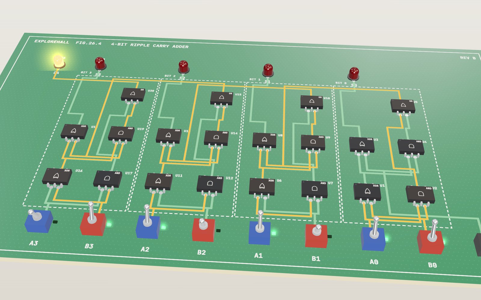
How logic gates add numbers: sum bits and carry bits
Adding 7 and 9 on this board takes 20 gates, and the last carry lands 8 gate delays after you flip the switches.
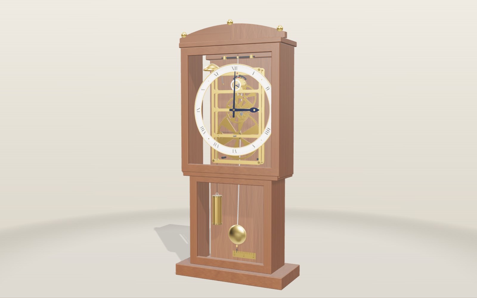
How a pendulum clock works, and why its length sets the time
A pendulum clock counts seconds with one rod 99.4 cm long. Change its length, its temperature and its place on Earth, swap four escapements and see how many seconds a day each costs.
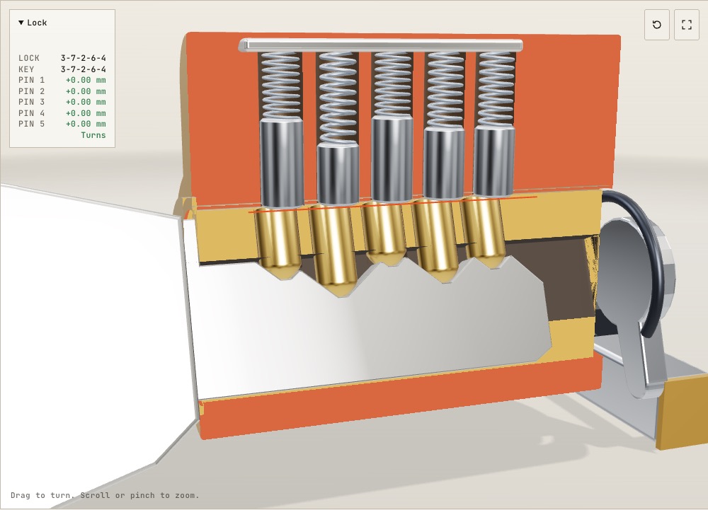
How does a pin tumbler lock work inside? A 3D cutaway
On a common Schlage key one cut depth differs from the next by 0.381 mm, and that small step is enough to keep a wrong key from turning.
How a QR code is read
Cover 30 % of a QR code with your hand and a phone still reads it. Cover one corner and it does not.
How a 3D printer works, layer by layer
A 20 mm cube printed in 0.2 mm layers is exactly 100 layers, each drawn by a nozzle 0.4 mm wide.
How windmills and watermills work
The sails of a Dutch mill are as wide as an eight-storey building is tall, and at 7 m/s they still take only about a fifth of the wind.