Loading the model
This device cannot show the 3D model. You can read the guide steps below as text.
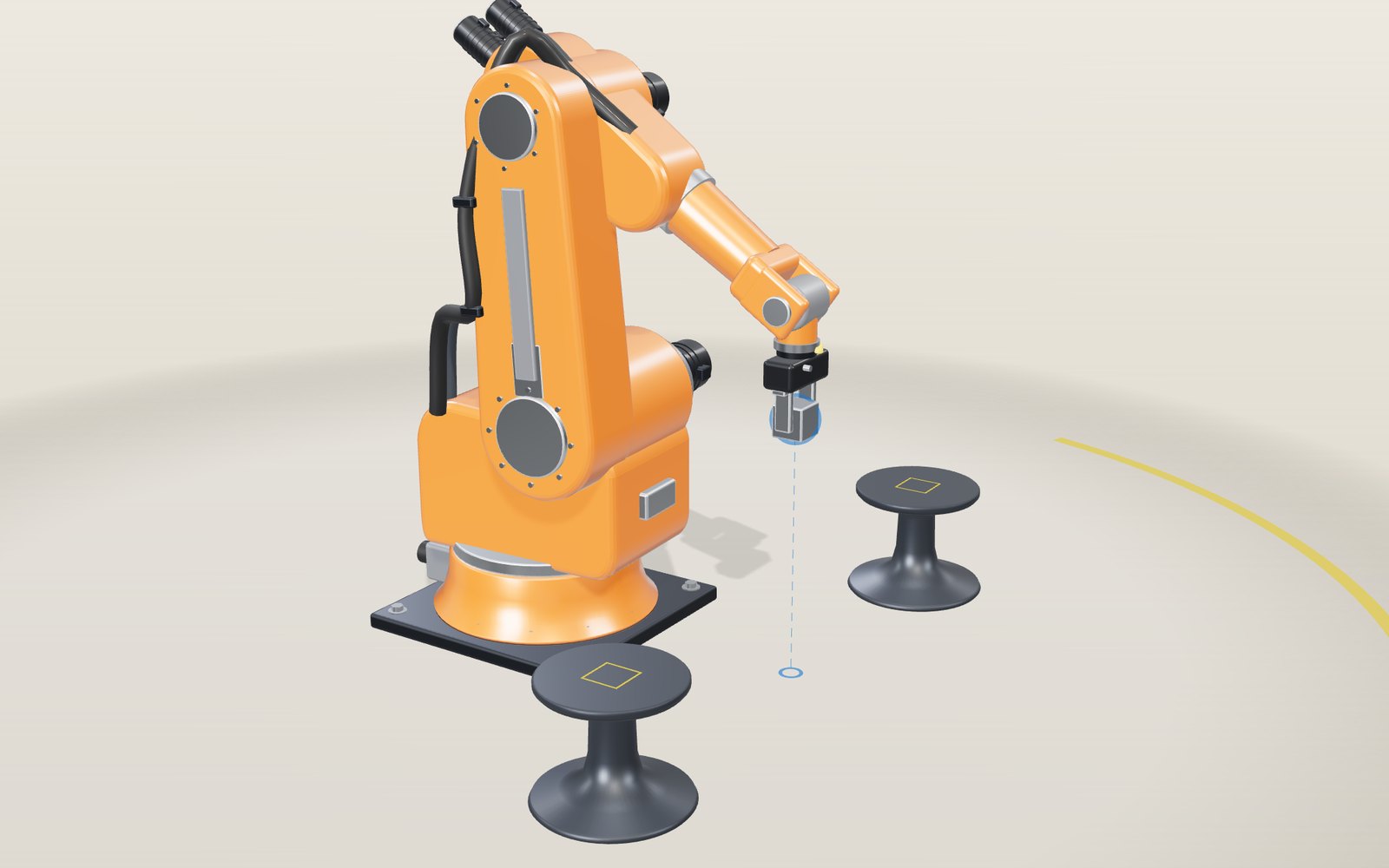
1 / 11 A six-axis arm between two stands The arm is bolted to the floor with a stand on each side. Six motors turn six joints, and the blue ball marks where the point between the fingers should go. At the moment it is carrying a steel block from one stand to the other.
Drag to turn. Scroll or pinch to zoom.
Guide Parts Controls
01 A six-axis arm between two stands The arm is bolted to the floor with a stand on each side. Six motors turn six joints, and the blue ball marks where the point between the fingers should go. At the moment it is carrying a steel block from one stand to the other.
02 J1 turns the whole arm The turret sits on a large bearing and swings about the vertical axis. Everything above it goes along, so J1 alone decides which way the arm faces. The model allows 170° either way.
03 Shoulder and elbow set the reach J2 leans the upper arm and J3 tilts the forearm. Between them they can put the wrist anywhere in the blue area, which shows where the fingertips can go with the gripper at its current angle. At the outer edge the arm is fully stretched.
04 Three wrist axes meet in one point J4 rolls the forearm, J5 bends the wrist and J6 rolls the flange. Their axes cross at the wrist centre, so the wrist can point the gripper in a new direction while that point stays still.
05 Drag the ball Drag the blue ball with a mouse or a finger, and the camera stays put while you do. The arm works out all six angles on every frame and follows. The ball turns red when the point is out of reach or a joint is at its limit.
06 When J4 and J6 line up The gripper is held level while the tip slides 44 cm sideways at 250 mm/s. Halfway along it passes 20 mm from the line where J5 is zero. The tip moves at an even pace, yet J4 swings through 39° in the middle 20 mm and peaks near 510° per second.
07 Picking up a block Above the block the arm lowers in a straight line, closes the fingers and lifts. While J1 swings 88° across to the other stand, J6 turns with it so the block does not spin in the fingers.
08 Collaborative mode Now the tip is held to 250 mm/s, the reduced-speed limit in ISO 10218-1. The 1.2 m transfer that took 1.8 seconds takes 7.2. Collaborative robots also cap the force they can press with, which the text below explains.
09 Where the arm loses a direction The reach area is now coloured by how freely the wrist centre can move. Near the pale bands the arm is close to stretched out, or the wrist centre is close to the J1 axis, and one direction of motion needs very fast joints. The bar in the readout shows the same measure for the whole arm, wrist included.
10 Two ways to make the same move The tip slides 44 cm past the wrist singularity in a straight line, drawn in blue. Run the joint move from the Controls tab and an orange curve appears: it is about 5 mm longer, but J4 peaks near 10° per second instead of about 510.
11 A real arm from its DH table The see-through arm is a UR7e, built from the six rows of a, d and α that Universal Robots publishes. A numerical solver puts its flange on the same ball. Pick other arms in the Controls tab and compare their joint angles, reach and the torque their shoulders need.
Base A steel plate held by four bolts and a cast housing with the power and signal connectors at the back. It carries the weight of the arm and the reaction to every move. Turret (J1) Turns on a large bearing about the vertical axis, up to 170° either way. Its motor sits on top at the back. J1 decides which direction the whole arm faces. Shoulder (J2) The largest motor and gearbox on the arm, because it lifts everything above it. The shoulder axis is 520 mm above the floor and 160 mm in front of J1. Upper arm A 620 mm cast link from the shoulder axis to the elbow axis. In the model it can lean 60° back and 100° forward from upright. Elbow (J3) Tilts the forearm relative to the upper arm, from 85° up to 80° down. Together with J2 it sets how far out and how high the wrist sits. Forearm (J4) A housing with the three wrist motors at its back, and a tube that rolls about its own axis (J4). The wrist centre is 600 mm from the elbow axis. Wrist (J5, J6) J5 bends the wrist up to 125° and J6 rolls the flange. The axes of J4, J5 and J6 cross in one point, the wrist centre. Gripper Two parallel fingers on a rail, opened and closed by the gripper body. The tool centre point sits between the fingertips, 240 mm from the wrist centre. Dress pack Conduits that carry power, signals and air from the turret to the forearm. They are clipped to the links and leave slack at each joint so they bend instead of twisting. Target The point the tool centre point should reach. Drag it and the inverse kinematics solver sets all six joints. It turns red when the point is out of reach or a joint is at a limit.