FIG. 03How It Works
How does a pin tumbler lock work inside? A 3D cutaway
On a common Schlage key one cut depth differs from the next by 0.381 mm, and that small step is enough to keep a wrong key from turning.
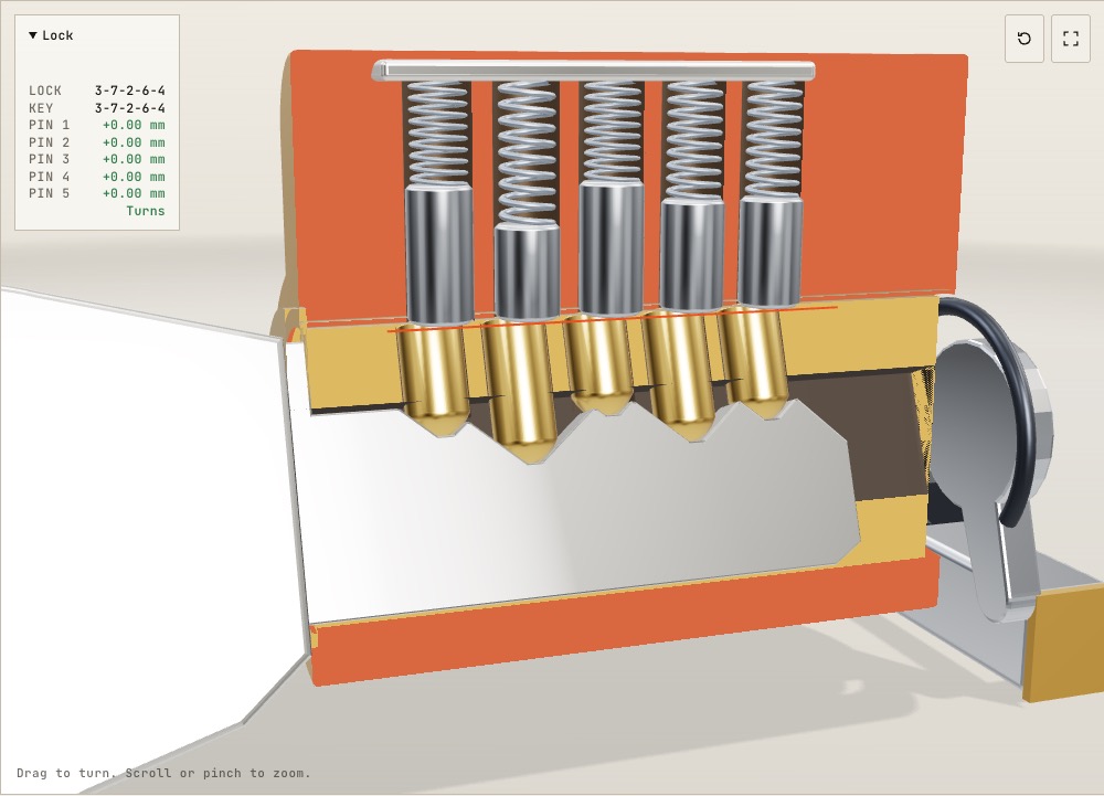
This device cannot show the 3D model. You can read the guide steps below as text.
1 / 8 The whole cylinderThe front half is cut away so you can see into the five pin chambers. Watch the demonstration run, or drag to look from another side.
Drag to turn. Scroll or pinch to zoom.
What the model shows
How does a pin tumbler lock work inside? The right key raises every pin joint to the shear line; cut depths differing by a few tenths of a millimetre can leave a pin blocking rotation. Why does your front door key open your door and not your neighbour's, when the two keys look almost the same? The answer sits in a row of small brass and steel pins inside the lock, and in cut depths that differ by a few tenths of a millimetre. This model lets you watch those pins while a key goes in and the plug turns.
The model is a five-pin cylinder of the kind found in many house locks, cut down the middle so the inside is visible. The red faces are the cut surfaces of the housing and the gold faces are the cut surfaces of the plug, the part that turns. The pins, springs, key, cam and bolt are shown whole. The key cuts and pin lengths follow the published bitting specification for Schlage Classic keys, so the numbers in the readout are real dimensions rather than guesses.
There are four keys to try. The right key is cut 3-7-2-6-4. The wrong key is cut 5-2-8-3-6. A third key matches the right one except for a single cut that is one step too deep. The fourth key is yours: five sliders under Controls set its cut depths, and the model recuts the blade as you move them.
Why the plug can't turn on its own
A cylinder lock has two main parts. The housing is fixed to the door. Inside it sits the plug, a brass cylinder with a slot for the key, called the keyway. Turning the plug turns a cam at the back, and the cam pulls the bolt that holds the door shut. If nothing stopped it, any flat piece of metal pushed into the keyway would turn the plug.
What stops it is a row of holes drilled straight through the top of the plug and on up into the housing. Each hole holds a stack of two pins and a spring. The lower pin, the key pin, rests on the key. The upper pin, the driver pin, sits on top of it, and the spring pushes the whole stack down.
With no key in the lock, the springs push every stack as far down as it will go. Each driver pin then reaches part of the way into the plug while its top end is still in the housing. A steel pin bridging the two parts like this works the same way as a bolt through a hinge: the plug can't turn without shearing five steel pins in half.
What the right key does
The top edge of a key is a row of V-shaped cuts. As the key slides in, the rounded tips of the key pins ride up and down over the cuts, which is why you can feel a key click as it goes in. When the key reaches its stop, each pin sits in the bottom of its own cut.
The boundary between plug and housing is called the shear line, and the model marks it in red. Each key pin is made exactly as long as the distance from the bottom of its cut to that line. A deep cut gets a long key pin and a shallow cut gets a short one. With the right key fully in, the top of every key pin is level with the shear line, so the gap between each key pin and its driver pin lies exactly where the plug meets the housing. Nothing bridges the two parts any more and the plug turns.
As the plug turns, the driver pins stay behind in the housing and slide on the plug's outer surface. The key pins travel round with the plug. After a quarter turn the cam at the back has pulled the bolt in. Turn back, and the pin holes line up again so the springs push the drivers down into the plug. Only then can the key be pulled out.
Why a wrong key fails
A wrong key lifts the pins to the wrong heights, and there are two ways for a pin stack to be wrong. If a cut is too deep, its key pin sits too low and the driver pin above it still hangs into the plug. If a cut is too shallow, the key pin is pushed up too far and now it is the key pin that reaches into the housing. Either way a pin bridges the shear line and the plug stays put. Pressing Turn key with a wrong key makes the plug twitch, and the pins that block it flash red.
With the wrong key in the model, the readout shows gaps of −0.76, +1.91, −2.29, +1.14 and −0.76 mm. A plus sign means a key pin sticks up into the housing; a minus sign means a driver pin hangs down into the plug. Every one of the five would be enough to block the plug by itself.
The third key is the more interesting one. It differs from the right key in a single position, where the cut is one step deeper: depth 3 instead of 2. The difference is 0.381 mm. Pin 3's key pin drops by that much, its driver pin dips 0.38 mm into the plug, and the lock stays shut.
The numbers, worked out
The Schlage service manual gives the root depth of each cut, measured from the bottom of the blade, and the length of the matching bottom pin. Depth 0 is the shallowest cut and depth 9 the deepest.
| Quantity | Value | How it follows |
|---|---|---|
| Step between depths | 0.015 in = 0.381 mm | from the root depth table |
| Root depth, depth 0 to depth 9 | 8.51 mm to 5.08 mm | 0.335 in − 0.015 in × depth |
| Key pin length, size 0 to size 9 | 4.19 mm to 7.62 mm | 0.165 in + 0.015 in × size |
| Root depth plus key pin | 0.500 in = 12.7 mm for every depth | 0.335 + 0.165 = 0.320 + 0.180 = … |
| Distance from shoulder to cut 1 | 0.231 in = 5.87 mm | from the spacing drawing |
| Spacing between cuts | 0.156 in = 3.96 mm | 0.3872 − 0.231 = 0.1562 in |
| Possible five-cut keys | 100,000 | 10⁵ |
| Keys that obey MACS 7 | 79,666 | counted cut by cut, see below |
| Depth tolerance | +0.002 in = 0.051 mm | a step is 0.381 ÷ 0.051 = 7.5 tolerances |
The fourth line explains why the lock works with only ten kinds of key pin. Making a cut one step deeper lowers the bottom of the cut by 0.015 in, and the key pin for that depth is 0.015 in longer, so the top of the pin always ends up 0.500 in above the bottom of the blade. In the model the bottom of the blade sits 12.7 mm below the shear line for the same reason.
The driver pins vary too, though less. The manual lists three top pins, 0.235, 0.200 and 0.165 in long, for bottom pins of size 0 to 3, 4 to 6 and 7 to 9. A longer key pin gets a shorter driver, so every stack fills its hole to roughly the same height and every spring is squeezed by a similar amount. The model uses those three lengths, which is why its driver pins are not all the same size.
The 100,000 figure assumes every combination of ten depths in five positions is allowed. In practice some are not, which is where the next section comes in.
Why neighbouring cuts can't differ by more than seven
The Schlage manual gives a figure called MACS, the maximum adjacent cut specification, and for this key it is 7. Two neighbouring cuts may differ by at most seven depths. A key with a 0 next to an 8, a 0 next to a 9, or a 1 next to a 9 is not allowed.
The reason is geometry. Each cut is a V with an included angle of 100°, so each side slopes at 50° from vertical, and the bottom of each V is a flat 0.031 in wide. The flat of one cut is centred 0.156 in from the next. Climbing the side of a deep cut, the blade rises by 1 ÷ tan 50° = 0.839 for every unit you move along it. From the edge of the deep cut's flat to the near edge of its neighbour's flat is 0.156 − 0.031 = 0.125 in, so the slope rises 0.125 × 0.839 = 0.105 in before it reaches the neighbour. That is seven steps of 0.015 in.
So a difference of seven depths leaves the shallow cut's flat just intact. A difference of eight is 0.120 in, a little more than the slope can climb, and the side of the deep cut eats into the shallow one. Its centre drops by about 0.002 in, the same size as the cutting tolerance. A difference of nine lowers it by 0.017 in, more than a whole step, and the key would no longer lift that pin to the right height.
The model shows this on its own, because it builds the blade from the same V shapes. Set your key to 0-9-2-6-4 and the readout warns that it breaks MACS 7. The first cut has been partly cut away by its neighbour, and pin 1 sits lower than a true depth 0 would put it.
Counting the keys that obey the rule takes a short calculation. Out of the 100 ordered pairs of neighbouring depths, six are forbidden (0-8, 0-9, 1-9 and the same three reversed). Building up the key one cut at a time and keeping only allowed pairs gives 79,666 five-cut keys out of 100,000, so about one in five combinations is ruled out by the shape of the cutter alone. For a six-pin cylinder the same count gives 753,754 out of 1,000,000.
How the model differs from a real lock
Real cylinders have features the model leaves out. The keyway in a real plug is a twisting profile with ridges called wards, which only a matching key blank can pass; the model's keyway is a plain slot. Master-keyed locks have an extra small pin in some stacks, so that two different keys can each line up a gap at the shear line. Many cylinders have six pins rather than five.
The plug diameter and pin diameter in the model are close to common sizes but are not taken from a published drawing. The model also lets the plug turn when every gap is within 0.06 mm of the shear line. That threshold is a modelling choice, not a figure from a manufacturer. The real limit depends on how much clearance there is between the pins and their holes, and between the plug and the housing.
This page explains how a lock decides between keys. It does not cover ways of opening a lock without its key.
Where the pin tumbler lock came from
The Yale cylinder is a modern development of a much older idea: movable pins can block a bolt or a rotating part. The two Yale generations contributed different stages to that development. The comparison with wooden locks below distinguishes the mechanism, the patent date and the date of a museum reconstruction.
Clearance, friction and security pins
The drawing makes the holes look perfectly aligned. A manufactured cylinder cannot be perfect in that way. A pin needs clearance in its hole or it will not slide; the plug needs clearance in the housing or it will not turn. Drilling, finishing, wear and dirt all affect the contacts. Even if the nominal positions of the holes are identical, their actual centres and diameters differ slightly. Under a turning load, some pins therefore contact the edges of their holes before others. The load is not shared equally among the stacks.
That uneven contact explains why the order in which pins resist motion matters to lock security. A pin pressed sideways against a hole has friction that a freely sliding pin does not have. The spring force is still present, but it is no longer the only force on the pin. Describing this contact is different from teaching a method of opening a lock: no tool sequence or manipulation procedure is needed to understand that an assembly with clearance can reveal information through its moving parts. Blaze's research treats locks as information-bearing mechanisms as well as barriers.
A spool driver has a narrow waist between wider ends. When the waist reaches the boundary between plug and housing, the plug can move a little while a wider end still prevents complete rotation. A serrated driver has grooves that create additional edges and possible contacts. These shapes are intended to make the mechanical feedback less straightforward than that of a smooth cylindrical driver. They do not change the height at which the correct key must place the true joint between pins. Nor do they make the cylinder immune to every attack. Their effect depends on the surrounding geometry, tolerances and other protective features.
The visible drivers in this model are plain cylinders. The simulation calculates vertical gaps; it does not calculate friction, elastic deformation or a sequence of binding contacts. A pin flashing red means that its calculated position blocks rotation. It is not a prediction of which pin would bind first in a physical cylinder. Likewise, the permitted gap of 0.06 mm is a numerical rule for the exhibit, not a test of resistance to manipulation. A product cannot receive a security rating from this animation.
Manufacturing precision also has an everyday cost. A mechanism must tolerate ordinary insertion, repeated use and its intended environment, rather than merely work when newly assembled on a bench. A worn key can have rounded shoulders or damaged cuts, and a door can put unwanted load on a bolt. Difficulty turning a key is therefore not evidence by itself that the bitting is wrong. Service and replacement decisions belong with the manufacturer or a qualified locksmith; forcing a jammed key can damage the key or cylinder.
What master keying does to the key space
A conventional master-keyed stack contains an additional short piece, often called a master pin or master wafer. Instead of a single joint between lower and upper pins, the stack has another joint. More than one lifting height can then place a joint at the shear line. This is convenient in a building where a room key should open one door and a maintenance key should open many. The extra joint deliberately makes the mechanical test less selective.
Consider an illustrative cylinder in which each of five stacks accepts two different heights, with all choices independent and mechanically valid. It can accept 2⁵ = 32 depth patterns, not merely the two named keys handed to the occupants and manager. This is an example, not a count for every master-key system. Actual schedules restrict depths, reserve combinations and use different patterns of mastering; MACS and keyway restrictions still apply. Some apparent combinations are not usable keys. The example shows why listing issued keys is not the same as counting every key that the mechanism would accept.
This also explains a common misunderstanding about capacity. Adding master wafers does not create more independent private rooms without a cost. It adds accepted relationships between keys and cylinders. A designer has to avoid unintended interchange, where an unrelated change key operates a door it was not meant to open. Depths may be reserved for the master system, and available changes must be allocated so that groups remain distinct. The number of safe assignments is therefore smaller than the raw count of arbitrary strings of digits.
Matt Blaze's paper, published in IEEE Security & Privacy in 2003, examined this as a rights-amplification problem. Possessing legitimate access to a limited part of a system could reveal information useful beyond that authorised access. The paper is important here because the weakness is not simply that a pin is made badly: it arises from the access structure built into the cylinder. This exhibit does not reproduce the paper's attack procedure. The relevant lesson for owners is to treat a master-key plan as a security design, with records and controlled distribution, rather than as a bigger pile of ordinary keys.
The earlier count of 79,666 keys has a narrower meaning. It counts five-position sequences that satisfy the stated adjacent-depth rule. It does not promise that a manufacturer sells that many mutually exclusive, master-keyed cylinders. It also does not give the probability of entry into a building. Keyway compatibility, actual key allocation, additional locking features and the door assembly all intervene between a combinatorial count and a security claim.
Reading cylinder standards
EN 1303 concerns cylinders and their original keys for building locks. Its subject includes durability, strength, corrosion and key-related security, with tests and classifications rather than a single claim that a lock is good. A classification needs its edition and its individual fields to be meaningful. The DIN catalogue identifies the 2015 edition as replaced by DIN EN 1303:2026-08. An older certificate should therefore be read as evidence about the edition and product it actually names, not silently presented as a result under a newer edition.
ANSI/BHMA A156.5 covers cylinders and input devices for locks. The published scope distinguishes operational and strength requirements. Its grades describe performance under specified tests; they are not a count of pins and not a guarantee that a particular door cannot be opened. ANSI/BHMA A156.30 addresses high-security cylinders separately. Its public scope distinguishes high-security levels from grades and notes that an assembly takes the grade of its lowest graded component. A strong cylinder does not upgrade a weak lock body by association.
There are practical reasons to keep the categories separate. A cylinder can survive many cycles but have limited resistance to a particular attack. Another can resist an attack yet be unsuitable for a corrosive environment. Installation may leave a cylinder exposed beyond its protective hardware, or the frame may be the weaker component. The standard's laboratory conditions make product comparisons repeatable, but they cannot reproduce every door, installation and maintenance history.
When reading a specification, ask for the exact product, the standard designation and edition, the claimed class or grade, and the test or certification evidence. A phrase such as “security pins” names a component feature, not a certificate. A large number of theoretical combinations describes a different property again. The five-pin model on this page carries no EN or BHMA classification. It illustrates the geometry that a tested commercial product may use, while leaving out much of what a standards laboratory measures.
Wooden locks and the Yale cylinder
A wooden pin lock and a modern cylinder share the idea that the key puts movable obstructions in positions that allow a larger part to move. They do not use identical motion. In the wooden arrangement, pins drop into holes in a sliding bolt and the key raises them clear. In the cylinder, lifting too far can be just as obstructive as lifting too little, because either member of a stack can bridge the boundary. The split stack is what makes the correct height matter in both directions.
Museum objects need careful dating. The Science Museum Group describes an “Ancient Egyptian lock” in its collection as a reconstruction made around 1912. A reconstruction demonstrates a mechanism; its manufacture date is not the date when ancient people first invented that mechanism. MIT's Lemelson account describes large wooden locks used in ancient Egypt around 4,000 years ago. That broad history does not establish an exact surviving specimen or prove that every later pin lock descended through one documented chain.
Linus Yale Sr.'s work in 1848 and Linus Yale Jr.'s cylinder patent in 1861 belong to the development of the modern form, not to the first use of movable pins anywhere. The patent dated 29 January 1861 is primary evidence for what was claimed at that date. The later small flat serrated key made the arrangement compact enough for everyday door hardware. Museum biographies, patents and reconstructions answer different historical questions, so they should not be treated as interchangeable dates for a single invention.
Checks to make on the screen
Begin with Right key and watch the joints rather than the coloured tops of the drivers. The joint must reach the shear line in every stack. Compare it with Wrong key and then One cut too deep. The last comparison isolates a single changed cut: the rest of the lock is unchanged, yet one obstruction is enough. This is a test of position, not of the total upward force on all the pins.
Choose Your key and set the five sliders to 3-7-2-6-4. The result should reproduce the right key because the same depth sequence produces the same supporting heights. Change only the third slider from 2 to 3. The gap changes by 0.381 mm, even though the blade still looks almost identical at a distance. The digital readout is useful precisely because the perspective view makes small differences hard to judge.
For a separate geometry check, use 0-9-2-6-4 and observe the Over MACS 7 warning. Compare the first two cuts with the earlier legal sequence. The warning does not mean the program has discovered a secret key: it means the proposed cuts interfere geometrically. Finally return to Right key before turning the plug and follow the cam to the bolt. Distinguish the cylinder's decision about the key from the bolt's job of holding the door. These screen experiments concern the supplied virtual keys only; they are not instructions for manipulating a real lock.
Questions
What is the shear line?
It is the boundary between the plug, which turns, and the housing, which doesn't. A lock opens when the gap between each key pin and the driver pin above it sits exactly on that boundary, so that no pin crosses from one part into the other.
Why do the pins have different lengths?
Each key pin is as long as the distance from the bottom of its cut to the shear line. On a Schlage key, the root depth plus the pin length always comes to 0.500 in, so a cut that is 0.015 in deeper needs a pin that is 0.015 in longer.
How many different keys are possible with five pins and ten depths?
There are 10⁵ = 100,000 combinations in theory. The MACS 7 rule removes those with a 0 next to an 8 or 9, or a 1 next to a 9, leaving 79,666. Master keying cuts the number further: for its full size cylinders, Schlage gives 4,096 theoretical changes per keyway when master keyed with two-step progression.
What happens if one cut is only one step off?
The pin in that position ends up 0.381 mm too high or too low. That is far more than the 0.051 mm cutting tolerance, and enough for a pin to bridge the shear line. In the model, the key with a single cut one step too deep does not turn.
Why does the key have to be turned back before it comes out?
While the plug is turned, the top of each key pin presses against the solid inside of the housing, so the pins can't rise to let the slopes of the key slide under them. Back at the starting position the holes line up again and the pins can lift.
What is a master key?
In a master-keyed lock some pin stacks contain an extra short pin between the key pin and the driver. That gives those stacks two gap positions, one for each key, so both the tenant's key and the building manager's key can line up a gap with the shear line.
Why does the key click as it goes in?
The rounded tips of the key pins drop into each cut and are pushed up again by the slopes between cuts. Each drop is a small tap of a spring-loaded pin onto metal.
Do security pins make a lock impossible to open without its key?
No. Their shapes complicate mechanical feedback but do not eliminate every weakness. A product's tested performance, installation and the rest of the door matter. The model contains plain drivers and cannot measure attack resistance.
Is the theoretical number of keys a security grade?
No. A combinatorial count says how many patterns meet stated rules. A grade records performance against specified tests under a named standard and edition. These are different claims.
Does a stiff key always mean the cuts are wrong?
No. Wear, contamination or unwanted load from the door can also interfere with movement. Consult the manufacturer or a qualified locksmith instead of forcing a jammed key.
Eight structures and eight different clearance tests
The collection changes the mechanism rather than merely changing its colour. The original pin cylinder remains the dimensional reference. The other seven sections are schematic models: their lengths, codes, angular steps and clearances are selected for visibility, not copied from a commercial product. A complete assembly would hide much of what happens inside, so each section leaves a large opening in the outer shell. The mechanism selector and catalogue cards lead to the same scenes. Selecting a historical card chooses a related principle; it does not claim that the displayed geometry reproduces the museum object named in that card. In particular, the Bramah card is a comparison with the lever scene, not a reconstruction of the Bramah slider lock. That distinction matters because similar looking keys can operate quite different internal mechanisms.
A disc detainer replaces the row of vertically lifted pin interfaces with independently rotating elements. Each disc has a gate at a particular angular location. When the gates agree, they provide a continuous space for a sidebar. The bar can then leave the fixed housing and allow the rotating assembly to move. In the teaching section, a wrong key leaves one disc visibly turned out of line. The error is angular rather than a vertical distance in millimetres. ABLOY describes rotating detainer discs as the operating principle developed by Emil Henriksson in 1907, followed by patenting and industrial production in 1919. Those dates belong to that manufacturer's history. They are not dates for every possible disc mechanism. The displayed five disc arrangement is a simplified example and should not be used to infer a current manufacturer's code system, number of discs or security classification.
A wafer cylinder uses thin moving plates. The key enters an opening in each plate and positions it relative to the outline of the plug. A wafer extending beyond that outline still engages the fixed shell, so the plug cannot rotate. Correct positioning brings the obstructing edges within the rotating envelope. Patent publication US20060032280A1 describes this general background and a particular improvement involving sidebars. The exhibit shows the basic plate clearance principle, not all of that patent's additional features. It is therefore possible for both statements to be true: the model is a wafer lock, and the patent illustrates a more elaborate wafer lock than the one on screen. Looking at the part that actually blocks motion is more informative than judging a lock by whether its key has one cut edge or two.
A lever lock asks a different geometric question. The key raises levers about pivots, and a fence attached to the bolt must find a passage through their gates. If a gate is too high or too low, the fence meets metal and the bolt stays put. The output of such a mechanism can be a translating bolt rather than a rotating cylinder. This is why the lever scene does not need to imitate a pin cylinder's quarter turn to demonstrate a valid release. The gate alignment and bolt travel are separate motions. The illustrated lever positions and their spacing are teaching choices. They are not a measured Chubb detector mechanism. The historical 1818 Chubb example adds a detector response to interference, while the plain lever scene only illustrates the gate condition that permits ordinary opening.
A warded lock has fixed obstructions rather than a row of moving code elements. Slots and clearances in the key bit let it pass those obstructions and reach the bolt mechanism. The Smithsonian Cooper-Hewitt collection catalogue provides historical context for keys and locks, including the relationship between key shapes and internal mechanisms. The model uses exaggerated fixed wards so the visitor can distinguish a clearance cut from a cut that positions a moving tumbler. A decorative, complicated key outline is not automatically a large set of independent code choices. Fixed obstructions, movable levers and split pin stacks should not be counted by the same formula. The warded scene consequently demonstrates compatibility and blocked rotation without pretending to give a universal number of possible warded keys.
The tubular scene rearranges the pin interfaces around a circular keyway. The key is hollow, and its rim presents cuts to axial pin stacks. US7150168B1 describes a tubular pin tumbler unit in which an improper key leaves a pin extending between the fixed and rotating seats. That is the same obstruction test as the familiar cylinder, viewed along a different direction. A circular layout does not by itself imply a particular number of pins, a particular code capacity or a particular resistance to attack. Five stacks are shown here to make comparisons with the original five pin model easier. The actual patent drawings should be consulted for the specific arrangement disclosed there. The scene's axial distances remain model values and are not dimensions for making a key.
The dimple scene puts the reading surface on the broad face of a key. Pins can approach from a side rather than all standing above one cut edge. A depression positions a pin, and an incorrect depression leaves an interface away from the boundary needed for rotation. Patent US20100199731A1 describes a more elaborate cylinder with depressions on opposing faces and rotating pins. The exhibit intentionally omits the twisting function and associated tracks; it shows only the depression and clearance relationship. This limitation is stated because the word dimple describes the key's visible features, not one universal internal design. A dimple key can be part of a simple mechanism or one with additional constraints. Counting visible dimples cannot establish how many independent conditions the whole product checks.
The master keyed scene adds a short intermediate segment to a pin stack. With a change key, one interface can coincide with the rotating boundary. With a master key, a different interface can coincide with the same boundary even though the complete stack has moved by a different amount. The mechanism therefore accepts two distinct lift patterns without changing its housing. The displayed extra segment is not a second spring and should not be mistaken for one. In a complete product, pin lengths, permissible steps and the key system's rules must all be designed together. The two valid patterns in this scene are deliberately simple so the two interfaces can be seen. They are not a recommendation for designing a building's master key system or a claim about any particular manufacturer's hierarchy.
Contact order is a model of manufacturing tolerance
A drawing often shows every chamber exactly on one straight line. A manufactured assembly has small deviations in hole position, surface finish and fit. Under rotational load, these deviations can make one element contact the surrounding material before another. The binding scene exaggerates offsets so this order becomes visible. Its displayed values, 0.03, 0.05, 0.02, 0.06 and 0.04, are dimensionless teaching values, not measurements of a lock. The smallest remaining offset reaches contact first. The resulting sequence is not simply left to right, and changing the offsets would change it. The load control and next contact control illustrate that relationship without supplying real tool dimensions, forces or an operating procedure. The little arm and probe are symbols for load and displacement, not working tool drawings.
A spool shaped driver has a narrow waist between wider ends. A serrated driver has grooves along its length. If the geometry near a boundary is no longer a plain cylinder, contact under load can occur in additional places. The same displacement can produce different resistance depending on what surface is touching. This is a qualitative explanation of why shape changes mechanical feedback, not a simulation of friction, elastic deformation or a successful attack. The comparison selector replaces the visible drivers with these three profiles while retaining the original key test. It does not calculate a security score. No conclusion about a product's certification, expected delay or suitability for a particular door follows from selecting a more complicated looking pin in the exhibit.
The impulse scene addresses a different physical idea: colliding masses can exchange momentum and briefly separate. A short pulse can produce motion without maintaining the geometry required for sustained rotation. The animation exaggerates that separation and returns the masses to their starting positions. It does not compute elastic contact, exact impact energy, spring damping, material hardness or timing. Those omissions prevent it from predicting the response of any actual cylinder. The educational question is why a momentary clearance and a persistent open state are not the same event. This scene is not a sequence for preparing a key or applying an impact to a lock. For real security decisions, use the manufacturer's tested resistance information and the relevant standard rather than an idealised animation.
Counting patterns with an adjacency constraint
For n positions and d available depths, independent choices give d to the power n patterns. Independence is the important assumption. If an adjacent pair must differ by no more than m steps, not every depth can follow every other depth. The laboratory keeps a row of counts indexed by the last depth. Initially every available depth has one one-position pattern. To append a new depth j, it adds the previous counts whose final depths i satisfy the inequality absolute value of i minus j at most m. Repeating that operation until all n positions have been filled gives the constrained total. Adding the final row counts patterns, not physical keys that a manufacturer has promised to sell.
For the displayed Schlage example, five positions and ten depths produce 100,000 unrestricted arrays. With MACS 7, the recurrence gives 79,666. With MACS 0, a depth can only follow itself, leaving ten constant arrays regardless of how many positions are added. These limiting cases are useful checks on the calculation. Small systems can also be checked by explicitly listing every array and rejecting those that break the neighbour rule. The independent enumeration and recurrence agree in the exhibit's test cases. No random sampling is needed. The count can nevertheless overstate the usable key space because it does not include keyway restrictions, reserved codes, wear allowances or the complete rules of a manufacturer's key system.
An extra interface creates a different kind of count. If each of k independent pin stacks can clear at either of two distinct heights, their Cartesian product has at most two to the power k accepted lift patterns. Five such stacks would therefore permit at most 32 arrays in this simplified model. Some may be removed by adjacency rules or may not correspond to usable keys. Matt Blaze's research on master keyed locks explains why unintended combinations are important to consider alongside the intended change and master keys. This upper bound is not the number of authorised people and not the number of cylinders in a building. A single authorised key can operate many cylinders, while several accepted arrays may never have been issued as keys.
Historical claims and modern access control
The reconstruction of an Egyptian wooden pin lock demonstrates the older idea of lifting obstructions out of a bolt's path. It should not be read as a dimensionally measured survivor of a particular ancient door. The Yale patents of 1861 and 1865 document later mechanisms and can be consulted as primary drawings. Bramah entered the lock business in 1784 with a slider principle, distinct from a plain lever lock. Linda Hall Library discusses both Bramah's work and the 1818 Chubb detector lock, using historical illustrations. These are separate developments, not a single straight sequence in which every new mechanism made all earlier mechanisms disappear. Different costs, manufacturing capabilities and applications can keep several principles in use at the same time.
An electronic access system can replace or supplement the mechanical decision with a credential reader and controller. That changes how permission is represented and revoked, but a bolt or other physical restraint still has to move. The eight mechanical scenes do not simulate electronics, networking, batteries or emergency release. Nor do they compare whole door assemblies, where installation and surrounding materials can dominate the result. Their purpose is narrower: identify the obstruction, identify the permitted clearance, and distinguish the key's motion from the final output motion. That method makes a comparison useful without confusing an attractive cutaway with a laboratory test or a certification report.
Is a Bramah lock the same thing as the lever scene?
No. Bramah's slider principle differs from the pivoted lever and fence principle shown here. Its catalogue card links to a related comparison scene and to historical reading, not to a faithful reconstruction of the challenge lock.
Does a circular or dimple key guarantee greater security?
No. Those terms describe visible geometry and sometimes families of mechanisms. They do not specify the whole assembly, its testing, its installation or every additional condition it checks. The model is not a product ranking.
Does completing a challenge certify that I understand a real lock?
No. The challenges test observations and arithmetic in a simplified teaching model. Real products include tolerances and additional features that the exhibit does not reproduce. Historical examples and patent disclosures also describe particular objects, not every product with a similar key.
Terms
- Plug: the cylinder inside the lock that turns with the key.
- Housing: the fixed body around the plug; also called the shell.
- Key pin: the lower pin in each stack, which rests on the key.
- Driver pin: the upper pin in each stack, pushed down by a spring.
- Shear line: the boundary between plug and housing.
- Bitting: the cuts on a key, written as a list of depths such as 3-7-2-6-4.
- Root depth: the height of the bottom of a cut, measured from the bottom of the blade.
- MACS: maximum adjacent cut specification, the largest allowed difference between neighbouring cut depths.
- Cam: the part at the back of the plug that turns with it and moves the bolt.
Sources
Schlage (Allegion), Cylinder dimensions and bitting specifications. https://commercial.schlage.com/content/dam/allegion-us-2/web-files/schlage/technical-documents/Schlage_Everest_Full_Size_Cylinder_Service_Manual_108484.pdf
National Inventors Hall of Fame, Linus Yale Jr.. https://www.invent.org/inductees/linus-yale-jr
US Patent Office / Google Patents, US31278A, 29 January 1861. https://patents.google.com/patent/US31278
MIT Lemelson, Linus Yale and the wooden pin lock. https://lemelson.mit.edu/resources/linus-yale
ASME, Linus Yale, Jr.. https://www.asme.org/topics-resources/content/linus-yale-jr
Matt Blaze, IEEE Security & Privacy, Cryptology and Physical Security (2003). https://www.mattblaze.org/papers/mk.pdf
Matt Blaze, Master-keyed lock vulnerability: research summary. https://www.mattblaze.org/masterkey.html
Matt Blaze, Keep it secret, stupid: research context. https://www.mattblaze.org/papers/kiss.html
Science Museum Group, Working model of Egyptian pin lock. https://collection.sciencemuseumgroup.org.uk/objects/co50403/working-model-of-egyptian-pin-lock-model-representation
Science Museum Group, Ancient Egyptian lock: reconstruction. https://collection.sciencemuseumgroup.org.uk/objects/co50298/ancient-egyptian-lock
DIN Media, DIN EN 1303:2015-08: scope and replacement. https://www.dinmedia.de/en/standard/din-en-1303/225357321
DIN, DIN EN 1303:2026-08: contents. https://www.din.de/en/getting-involved/standards-committees/nabau/publications/wdc-beuth:din21:401073981/toc-3712500/download
BHMA, A156.5-2020: Hardware Highlights. https://buildershardware.com/Portals/0/156_5%20HH%202020.pdf?ver=2020-06-17-203425-383
BHMA, A156.30: levels, grades and scope. https://buildershardware.com/Home-Sweet-Secure-Home/ansibhma-a15630-high-security-cylinders-product
BHMA, A156.30-2020: test categories. https://buildershardware.com/ANSI-BHMA-Standards/Hardware-Highlights/A15630-2020-High-Security-Cylinders
ABLOY history. https://www.abloy.com/global/en-us/about-abloy/history
USPTO US20060032280A1. https://image-ppubs.uspto.gov/dirsearch-public/print/downloadPdf/20060032280
USPTO US7150168B1. https://image-ppubs.uspto.gov/dirsearch-public/print/downloadPdf/7150168
USPTO US20100199731A1. https://image-ppubs.uspto.gov/dirsearch-public/print/downloadPdf/20100199731
USPTO US8695390B2. https://image-ppubs.uspto.gov/dirsearch-public/print/downloadPdf/8695390
USPTO US7530246B2. https://image-ppubs.uspto.gov/dirsearch-public/print/downloadPdf/7530246
Linda Hall Library, Joseph Bramah. https://www.lindahall.org/about/news/scientist-of-the-day/joseph-bramah
Linda Hall Library, Alfred Charles Hobbs. https://www.lindahall.org/about/news/scientist-of-the-day/alfred-charles-hobbs/
Cooper-Hewitt Museum, Keys and locks. https://archive.org/download/keyslocksincolle00coop/keyslocksincolle00coop.pdf
More exhibits
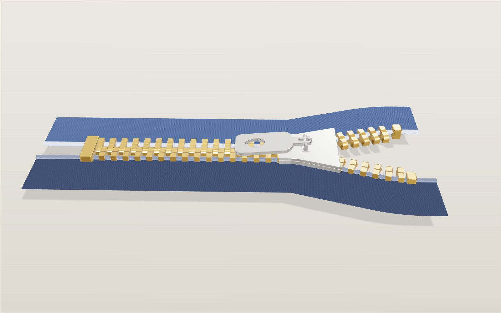
How a zipper works: how the slider locks the teeth
Nothing inside a zipper slider moves, yet the same Y-shaped channel locks the teeth on the way up and unlocks them on the way down.
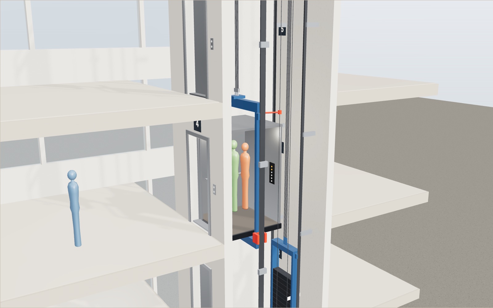
How does an elevator work? Counterweight and safety brake
A lift car full of people can weigh almost two tonnes, yet the motor that raises it only has to lift about a quarter of that, because a counterweight hangs on the other end of the ropes.
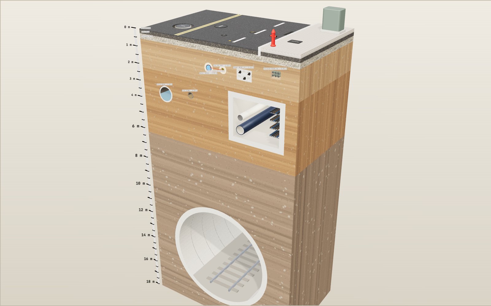
What is under the street
Korean road rules put a water main at least 1.2 metres under the road and a main sewer at least 3 metres down, so four kinds of pipe and cable all lie within the top 2 metres.
How to do CPR, use an AED, help someone choking and use a fire extinguisher
Push 100 to 120 times a minute, about 5 cm deep: with a bystander doing that, survival in Korea in 2024 was 2.36 times higher.
How windmills and watermills work
The sails of a Dutch mill are as wide as an eight-storey building is tall, and at 7 m/s they still take only about a fifth of the wind.
How does a vending machine recognise coins?
A 100 won coin is not attracted to a magnet, yet the magnet inside a vending machine is what tells it from a copper fake.
How to tie knots: 40 knots step by step
In one set of break tests a bowline kept about 63% of the rope's strength and a sheet bend about half.
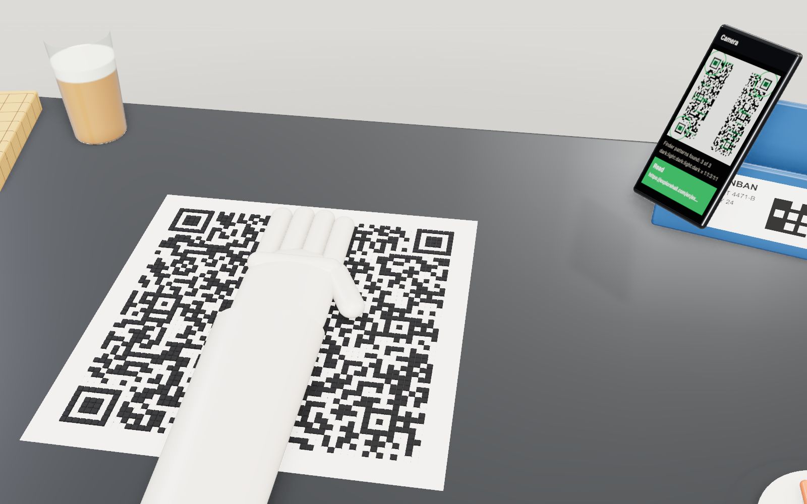
How a QR code is read
Cover 30 % of a QR code with your hand and a phone still reads it. Cover one corner and it does not.
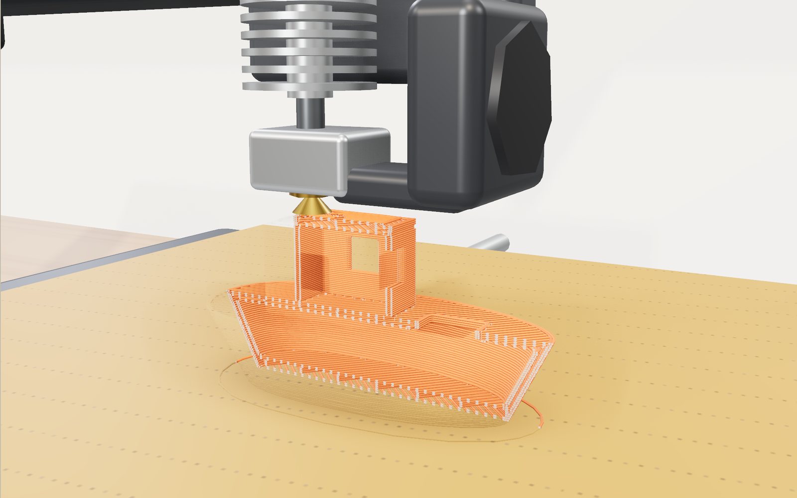
How a 3D printer works, layer by layer
A 20 mm cube printed in 0.2 mm layers is exactly 100 layers, each drawn by a nozzle 0.4 mm wide.
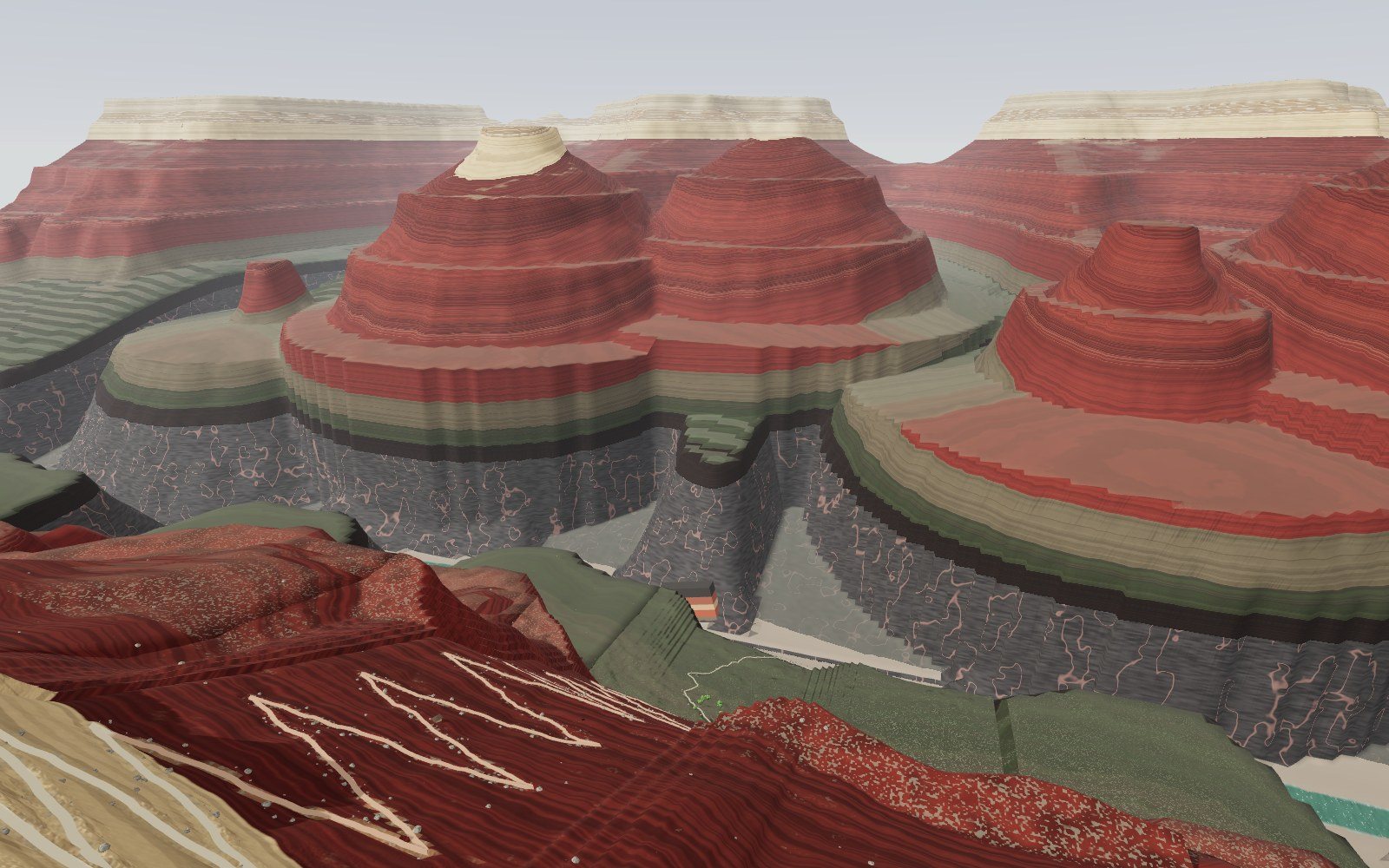
Walk down the Grand Canyon rock layers
Walk 1,360 m down the Bright Angel Trail through 13 rock layers, from a 270-million-year-old sea floor on the rim to 1.75-billion-year-old schist by the river.
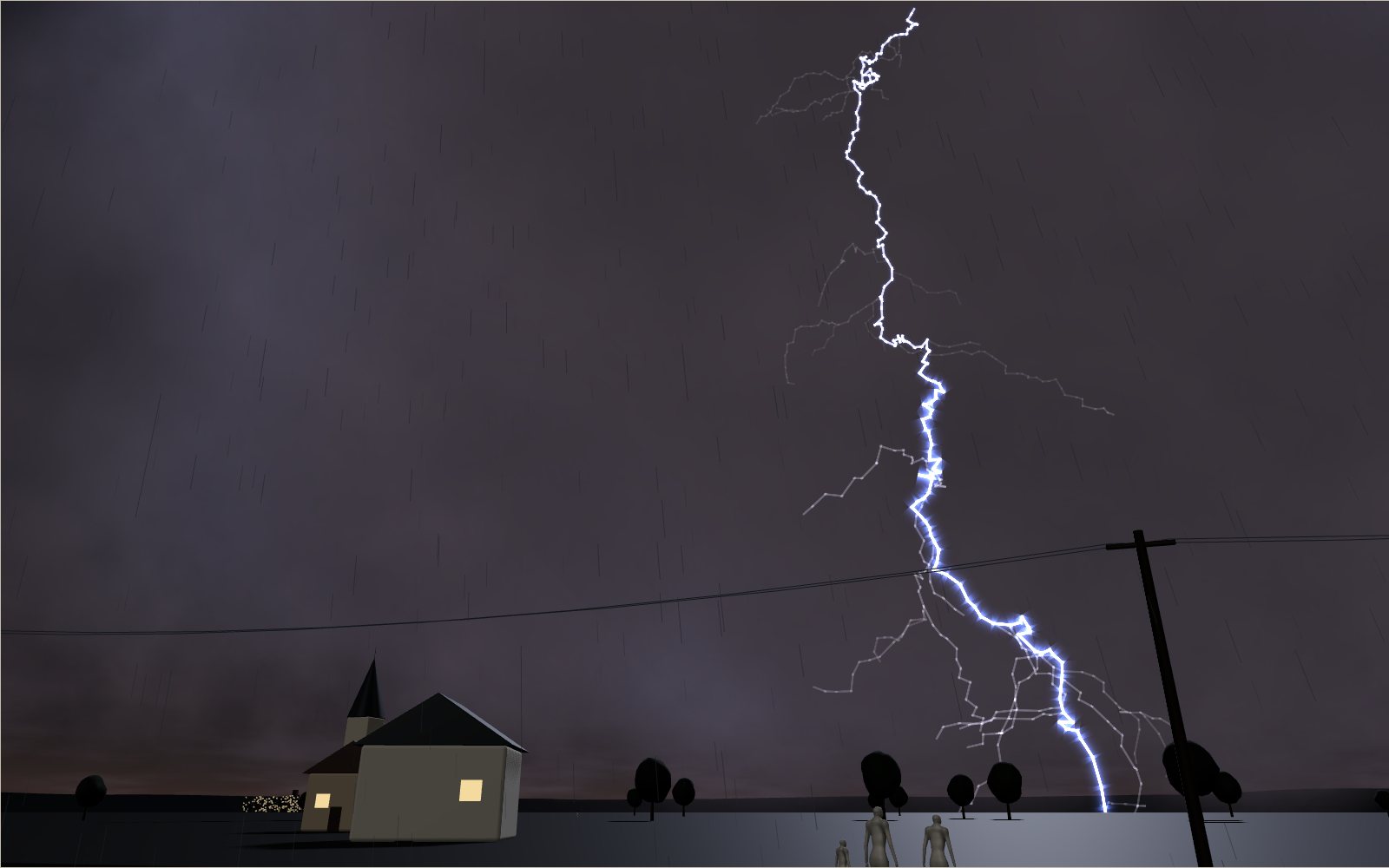
How lightning and thunder work
A lightning channel heats the air to about five times the temperature of the Sun’s surface, and its thunder needs about 3 seconds to cover each kilometre to you.
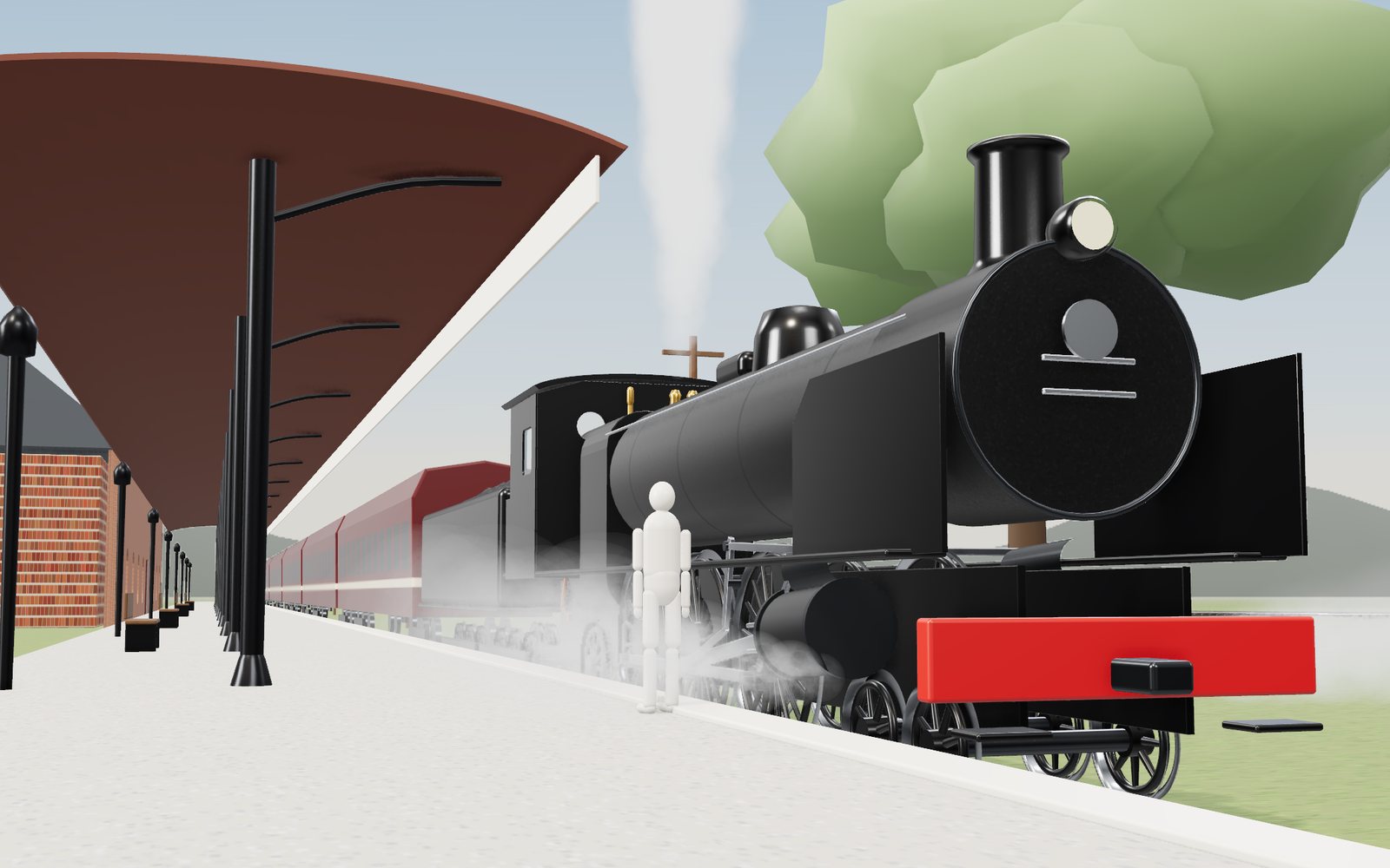
How a steam locomotive works
Mallard's driving wheels are 2.03 m across, taller than most people, and at its record 126 mph they turned almost nine times a second.