Loading the model
This device cannot show the 3D model. You can read the guide steps below as text.
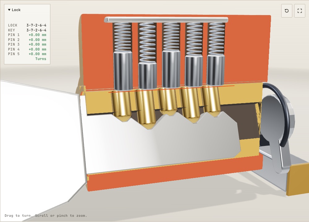
1 / 8 The whole cylinder The front half is cut away so you can see into the five pin chambers. Watch the demonstration run, or drag to look from another side.
Drag to turn. Scroll or pinch to zoom.
Guide Parts Controls
01 The whole cylinder The front half is cut away so you can see into the five pin chambers. Watch the demonstration run, or drag to look from another side.
02 With no key in The springs push every pin stack down as far as it will go. Each steel driver pin now sits partly in the housing and partly in the plug, which pins the two together.
03 The right key As the key slides in, the pins ride up and down over its cuts. When it is all the way in, each cut lifts its pin stack to one particular height.
04 The shear line The red line marks where plug and housing meet. With the right key, every gap between key pin and driver pin lands on that line. The readout shows each gap in millimetres.
05 A quarter turn Nothing crosses the line, so the plug turns. The driver pins stay up in the housing, and the cam at the back pulls the bolt.
06 A wrong key Different cuts lift the pins to the wrong heights. Some key pins stick up into the housing, some driver pins hang down into the plug. Either one is enough to stop it.
07 Off by one step This key has a single cut 0.381 mm too deep, the smallest step this system uses. Pin 3's driver pin dips 0.38 mm into the plug, and that alone keeps the lock shut.
08 Cut your own key This key starts as a copy of the right one, 3-7-2-6-4. When you move one of the Cut sliders under Controls, the key is recut and the readout shows which pin now crosses the line.
Housing The fixed outer body. Its tower holds the top half of each pin chamber. Plug The brass cylinder that turns. The keyway runs along its length, and the lower halves of the five pin holes are drilled through its top. Key Nickel silver blade with five cuts. Each cut depth is a multiple of 0.381 mm. Key pins Brass pins with rounded tips that ride on the key. They come in ten lengths from 4.19 mm, each 0.381 mm longer than the last, one for each cut depth. Driver pins Steel pins, 4.19 to 5.97 mm long depending on the key pin below. While one of them reaches into the plug, the plug cannot turn. Springs Push each pin stack down onto the key, or into the empty keyway. Spring cover Closes the top of the chambers so the springs have something to push against. Cam Fixed to the back of the plug. A quarter turn of the key swings it round. Bolt Pulled back by the cam when the plug turns. In a door, this is what holds it shut. Retaining clip Keeps the plug from sliding out of the housing.