FIG. 76How It Works
How does an elevator work? Counterweight and safety brake
A lift car full of people can weigh almost two tonnes, yet the motor that raises it only has to lift about a quarter of that, because a counterweight hangs on the other end of the ropes.
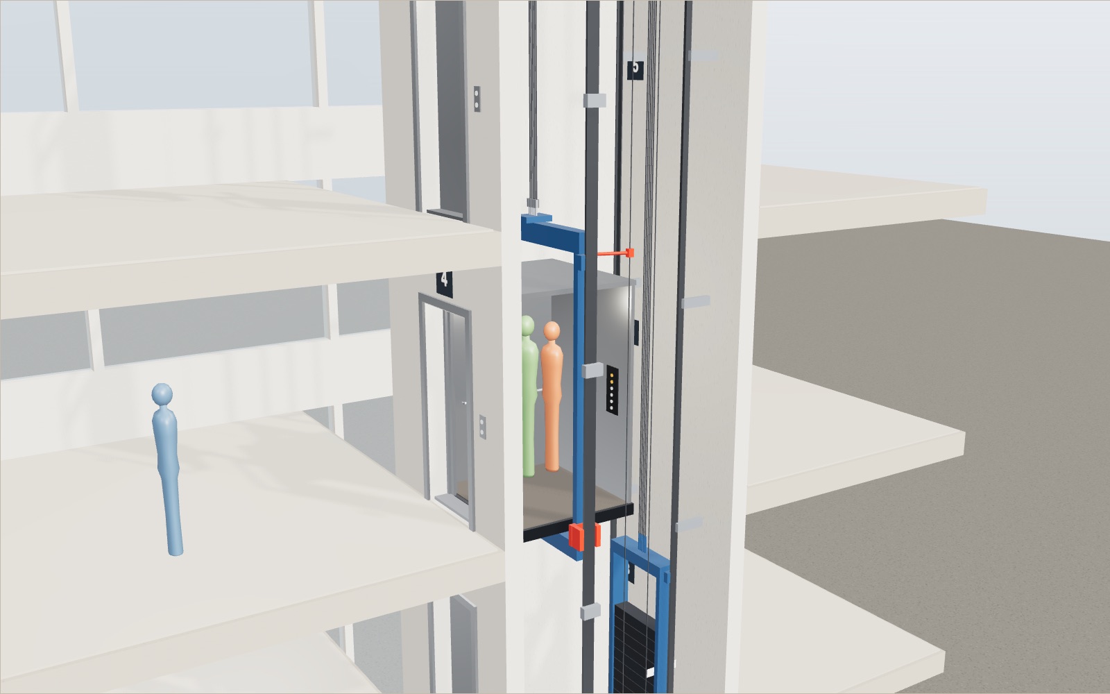
This device cannot show the 3D model. You can read the guide steps below as text.
1 / 10 A lift in sectionThis is a six-stop passenger lift cut open from the front. The car runs on rails in a concrete shaft. The counterweight runs beside it, and the machine sits in a room on top. Floors are 3 m apart, so the car travels 15 m from the bottom stop to the top.
Drag to turn. Scroll or pinch to zoom.
What the model shows
Step into a lift on the ground floor, press 6, and about ten seconds later the doors open 15 m higher. Nothing in the car tells you how that happened. There is no sound of a winch, no rope going taut, and the ride feels the same whether you are alone or squeezed in with twelve other people. This exhibit opens the shaft so you can see why.
The model is a passenger traction lift of a common size: six stops 3 m apart, a car that weighs 1,000 kg and may carry 1,000 kg, a counterweight beside it, and a gearless machine in a room above the shaft. None of it copies one maker's data sheet. Every mass and dimension is a model value, picked to sit in the normal range and to keep the arithmetic easy to follow. You can load the car with up to 13 passengers (counted at 75 kg each), press the call buttons on the right of the stage, hold the doors open, raise the rated speed and cut the ropes. The panel in the corner recalculates the torque, the work per trip and the safety numbers each time.
Why the ropes are not wound onto a drum
The obvious way to lift a box is to tie a rope to it and wind the rope onto a drum. Early goods hoists did exactly that, and small drum machines still exist. The trouble is that the drum must hold the whole length of rope, and the motor must lift the whole weight of the car and its load every time.
A traction lift does something different. The ropes are fixed to the car at one end and to the counterweight at the other, and in between they simply lie over a grooved wheel called the traction sheave. Nothing is wound up. When the motor turns the sheave, friction in the grooves drags the ropes along, so the car goes one way and the counterweight goes the other by the same distance. In the model the sheave is 640 mm across, and five ropes run side by side in its grooves. Next to it a smaller deflector sheave spaces the ropes out, so the counterweight can hang beside the car rather than directly under the machine.
Watch the red marks on the two sheaves while the car moves. They turn by exactly the rope travel divided by their radius, which is why the small deflector sheave spins faster than the big one.
The counterweight carries the car and about half the load
Here is the first number that matters. The counterweight in the model weighs 1,450 kg. That is the empty car (1,000 kg) plus 45% of the rated load (1,000 kg). Published descriptions of traction lifts give the same rule: the counterweight usually equals the car plus 40 to 50% of the capacity.
Why not simply match the full car? Because a lift is rarely full. If the counterweight matched the full car, the motor would have to haul an empty car up against 1,000 kg of extra counterweight, and an empty car is the most common case outside rush hour. Splitting the difference means that the car side and the counterweight side are equal at six passengers (450 kg), and the imbalance never gets very large in either direction.
Set the Passengers slider to 6 and look at the readout. "Car side minus counterweight side" reads zero. In this state the motor only has to overcome friction and accelerate the masses. Everything else is balanced by gravity on the other end of the ropes.
Checking the torque and the energy
The torque the motor must supply at a steady speed is the out-of-balance mass times g times the sheave radius:
T = (m_car + m_load − m_cw) × g × r
With 13 passengers the car side is 1,000 + 975 = 1,975 kg, so the imbalance is 1,975 − 1,450 = 525 kg. At r = 0.32 m that gives 525 × 9.81 × 0.32 = 1,648 N·m. Take the counterweight away and the motor has to hold the whole 1,975 kg: 1,975 × 9.81 × 0.32 = 6,200 N·m. The worst case over the whole range of loads drops to about 27% of what it would be without a counterweight.
| Passengers | Car side | Imbalance | Torque with counterweight | Without |
|---|---|---|---|---|
| 0 | 1,000 kg | −450 kg | −1,413 N·m | 3,139 N·m |
| 3 | 1,225 kg | −225 kg | −706 N·m | 3,846 N·m |
| 6 | 1,450 kg | 0 kg | 0 N·m | 4,552 N·m |
| 9 | 1,675 kg | +225 kg | +706 N·m | 5,258 N·m |
| 13 | 1,975 kg | +525 kg | +1,648 N·m | 6,200 N·m |
The minus signs are worth a look. With an empty car the counterweight side is heavier, so going up the motor has to hold the car back rather than pull it. The chart in the readout shows this as the red line crossing zero at six passengers, while the grey line (no counterweight) stays far above it.
Energy follows the same pattern. Lifting the full car from floor 1 to floor 6 (15 m) with a counterweight takes 525 × 9.81 × 15 = 77 kJ. Without one it takes 1,975 × 9.81 × 15 = 291 kJ, nearly four times as much. Averaged over every load from 0 to 13 passengers the difference is larger still: about 39 kJ per trip with the counterweight against 219 kJ without. When the counterweight side is the heavier one, the motor runs as a brake, and a modern regenerative drive can feed some of that energy back to the building instead of turning it into heat.
Why the sheave can grip the ropes at all
A traction sheave only works because both ends of the rope pull on it. Friction on a curved surface can hold a difference in tension, but only up to a ratio that grows exponentially with the friction coefficient and the angle of wrap. Sailors use the same effect when they take a few turns of line round a bollard.
In the model the tension ratio between the two sides is 1.45 with an empty car, 1.00 at balance and 1.36 with 13 passengers. Those are comfortable numbers. Without a counterweight there would be nothing on the other side of the sheave at all, and a traction drive could not work. So the counterweight does two jobs: it saves motor work, and it gives the sheave something to grip against. The UK Lifts Regulations put the second job in one sentence: lifts driven by friction pulleys must be designed to ensure the stability of the traction cables on the pulley.
How the car decides where to stop next
Press several buttons on the call panel and the car does not answer them in the order you pressed them. It follows a simplified collective control, the scheme that most single lifts use in some form:
- Keep going in the current direction while there is any call ahead.
- On the way, stop for buttons pressed inside the car and for landing calls going the same way.
- If the only calls ahead are going the other way, run to the farthest of them, then turn round.
- When nothing is left ahead, reverse, or wait with the doors shut.
The tour sets up a typical case. The car stands at floor 1. Inside, someone has pressed 5 and 2. On floor 3 someone wants to go up, and on floor 4 someone wants to go down. The car stops at 2, 3 and 5 on its way up, then comes back down to 4. The passenger on floor 4 waits a little longer, but nobody is carried in the wrong direction. Disk drives once used the same rule to move their read heads, and computer science still calls it the elevator algorithm.
The readout lists the planned stops after the word "next", and the list changes as soon as you press a button. A call that the car can no longer stop for in time (because it is too close to brake gently at 1 m/s²) is left for the return trip.
Tall buildings with banks of lifts use more elaborate methods. With destination dispatch, passengers enter their floor before they get in, and the controller groups people going to nearby floors into the same car.
Doors that lock before the car can move
A landing door that opens onto an empty shaft is the hazard the interlock exists to stop. Each landing door in the model has a lock on its header. When the doors close, a hook drops and a switch closes, and the small lamp beside the lock turns green. All six switches are wired in series in the safety chain, so one open door anywhere stops the whole lift.
The UK Lifts Regulations, which carry over the European essential requirements, state it plainly: an interlocking device must prevent, during normal operation, any start of the car unless all landing doors are shut and locked, and must prevent a landing door opening while the car is moving outside the landing zone. Turn on "Hold the doors open" and press another floor. The car stays put, the readout says why, and it leaves as soon as you let go of the doors and the lock closes.
What happens if the ropes break
This is the fear people bring into a lift, and it is the reason the lift became a passenger machine at all. In the model you can cut all five ropes with one toggle. The fall is shown at a quarter of real speed, because the real thing is over in about half a second.
Three parts take part. The governor sits in the machine room. Its own rope makes a loop down to a weighted pulley in the pit and is clamped to the car, so the governor turns whenever the car moves. Flyweights inside it swing outwards as speed rises. In the model it trips at 1.15 times the rated speed, 2.01 m/s for 1.75 m/s, and a jaw locks the governor rope. The car keeps falling for an instant, so the locked rope pulls up the linkage on the car frame. That linkage lifts the wedges of the safety gear into the narrowing gap beside each rail, and they squeeze the rail until the car stops.
The numbers are short. From rest, the car falls freely until it reaches 2.01 m/s, which takes 2.01 ÷ 9.81 = 0.21 s and 2.01² ÷ (2 × 9.81) = 21 cm. The model's progressive safety gear then brakes at an average of 0.6 g, so it stops in 2.01² ÷ (2 × 0.6 × 9.81) = 34 cm. About 55 cm in all. The counterweight, now free, falls onto its buffer in the pit.
The regulations ask for three things that you can see here. The lift must have an overspeed governor. The device that stops a falling car must be independent of the ropes that hang it. And it must be able to stop the car at full rated load and top speed without decelerating the passengers harmfully. They also require at least two independent ropes, each with its own anchorage, and buffers in the pit. The exact governor trip speed and the allowed deceleration range are set in the detailed lift standards. The 1.15 and 0.6 g used here are model values in a typical range.
How fast lifts in tall buildings go
The speed slider goes up to 21 m/s, the rated speed Hitachi reports for its lift in the Guangzhou CTF Finance Centre: 1,260 m/min, carrying people from the ground floor to the hotel lobby on the 95th floor, 440 m up, in about 42 s. The same lift comes down at only 600 m/min (10 m/s). Before it, the record belonged to Taipei 101, whose lifts reached 16.83 m/s in 2004. The double-deck lifts of the Burj Khalifa run at up to 10 m/s.
Raise the slider in the model and very little seems to happen. That is the point. With an acceleration of 1 m/s², a car needs v² ÷ a metres to speed up and slow down again. For 21 m/s that is 441 m, slightly more than the whole run in Guangzhou, which is why the time comes out at about 2 × √440 = 42 s, matching Hitachi's figure. In our 15 m shaft the car can only reach √15 = 3.9 m/s before it has to brake. Fast lifts only pay off in tall buildings, and even there the comfort limits on acceleration and the change of air pressure on the ears decide much of the design.
Where the model is simpler than a real lift
- Rope weight is left out. In a tall building the ropes themselves weigh hundreds of kilograms and shift from one side of the sheave to the other as the car moves, so long-travel lifts hang compensating ropes or chains under the car and counterweight.
- Friction, motor losses and the energy needed to accelerate the masses are ignored. The torque and work shown are the gravity part only.
- Real motion profiles also limit jerk (the rate of change of acceleration), so starts and stops are gentler than the constant 1 m/s² used here.
- The safety gear in the model grips at a fixed 0.6 g. Real progressive gear is set for the rated load and gives a deceleration that depends on the load in the car.
- The control follows one simple rule and ignores door reopening, load weighing (a real lift refuses to start when overloaded) and fire service modes.
A short history
The safety brake, not the lift itself, is the invention linked to Elisha Otis. Otis Elevator Company dates its business to 20 September 1853, the first sale of an elevator with his safety brake. In 1854, at the Exhibition of the Industry of All Nations in New York (the Crystal Palace Exhibition), Otis stood on a raised platform and had the hoisting rope cut. According to the company's own history, the platform dropped a few inches and then the brake stopped it, and Otis told the crowd "All safe, gentlemen, all safe." Three years later, on 23 March 1857, the first Otis passenger elevator went into service in the E. V. Haughwout Building in New York. Otis secured a patent in January 1861 and died a few months later.
Speeds have climbed since. Hitachi notes that its 1968 lift for the Kasumigaseki Building in Tokyo ran at 300 m/min, then the fastest in Japan; the Guangzhou lift runs at more than four times that.
How the numbers were checked
All values on the stage come from one set of formulas. The same formulas were worked through by hand and agree for: the counterweight, the balance point at six passengers, the torque and work for 0 and 13 passengers with and without a counterweight, the rope tension ratios, the trip times, Hitachi's 42 s for 440.4 m, the free-fall and stopping distances and five call sequences for the collective control. All 54 hand calculations agree.
Power is not the same as energy per trip
A motor must be chosen for how quickly it can do work as well as the energy of a complete trip. Imagine an unbalanced mass of 1,000 kg rising steadily at 3 m/s. These are calculation assumptions, not the load and speed of the car on the stage. Gravity pulls down with 9,810 N. Multiplying that force by the speed gives 29,430 W, or 29.43 kW of mechanical power. Raising the mass 15 m takes 147,150 J, or about 147 kJ, whether the steady part of the trip is fast or slow. Greater speed requires greater power but does not change that gravitational energy.
Now use the model's actual masses. With 13 passengers, only the 525 kg imbalance contributes to the steady gravitational power. At 3 m/s it requires about 15.45 kW. At the default 1.75 m/s it requires about 9.01 kW. Both ideal trips through 15 m transfer the same 77.25 kJ between the motor and the moving weights. These figures exclude acceleration and losses, just as the work readout does. They are not a recommended motor rating and are not electricity-meter readings.
Suppose, only for an illustration, that the conversion from electrical input to mechanical output were 80% efficient during steady lifting. Supplying 15.45 kW at the sheave would then need about 19.31 kW from the electrical supply. That assumed efficiency is not measured in this exhibit. A building's annual consumption also includes door operation, lighting and time spent waiting. You cannot obtain it by multiplying one ideal trip by the number of daily passengers, because passengers share trips and the loading changes.
A balanced car still has inertia
At six passengers the car side and the counterweight each have a mass of 1,450 kg. Their gravitational effects cancel at the sheave, but neither mass disappears. When the car accelerates upwards, the counterweight accelerates downwards. Both gain kinetic energy, so the motor must accelerate their combined 2,900 kg even though the static imbalance is zero.
For an ideal calculation at 1 m/s², with rope mass and rotating inertia omitted, the extra driving force is 2,900 N. At the model's sheave radius of 0.32 m, that corresponds to 928 N·m of acceleration torque. It is additional to the gravitational torque, which happens to be zero in this particular balanced case. When the same system reaches 1.75 m/s, its two translating masses together hold about 4.44 kJ of kinetic energy. Braking must remove that energy again. A real machine also accelerates its rotor and sheaves, and its drive has current and temperature limits.
This is why the readout's zero torque at balance should not be read as a promise that the lift needs no motor. It is zero steady gravitational torque. The model deliberately separates that simple comparison from the motion calculation. Changing the passenger count affects the torque display, but the exhibit does not simulate a motor struggling to achieve its commanded acceleration. In an actual lift, traction, available motor torque and the allowed ride profile have to be checked together.
The machine brake and the safety gear do different jobs
During normal service the drive slows the car before a landing, and the machine brake holds the stopped equipment. The overspeed governor and the safety gear address a different failure: a car moving too fast. The governor senses movement through its own rope, while the safety gear acts against the guide rails. The UK Lifts Regulations require the device preventing free fall to be independent of the car's suspension. A brake acting only on a traction sheave would not meet that purpose after every suspension rope had parted.
The rail grip is not a command to stop at the nearest floor, and it is not an ordinary passenger control. A stopped car may be between landings and still require a controlled rescue by competent personnel. Buffers in the pit provide another protective function at the end of travel; they are not substitutes for the governor and rail gear. The separate parts matter because one failure must not remove every way of arresting the car.
The screen's rope-cutting switch removes all five suspension ropes together so that this sequence is visible. It does not estimate how likely that event is. Likewise, the 55 cm result belongs to the stated model conditions, including its starting motion, trip threshold and assumed braking deceleration. It is not a guaranteed clearance for every installation. Never use an exhibit calculation to inspect, adjust or test a real lift's safety equipment.
Try the comparisons on the screen
Start with Passengers at 0, leave the rated speed at 1.75 m/s and call floor 6 from floor 1. Note the negative imbalance: the empty car is lighter than the counterweight. Repeat with six passengers, then with 13. The readout passes through zero and becomes positive. In each case the car still travels upwards when commanded. The sign describes the direction of gravitational motor effort, not the direction in which passengers have asked to travel.
Next compare a trip from floor 1 to floor 2 with one from floor 1 to floor 6. Their distances are 3 m and 15 m. With the assumed acceleration of 1 m/s², the shorter run can reach only about 1.73 m/s before it must brake. Turning Rated speed up to 21 m/s cannot make that short trip cruise at 21 m/s. Even the longer run reaches only about 3.87 m/s in the ideal triangular speed profile. These limits come from the available distance, not from a fault in the slider.
Finally, use Hold the doors open before requesting another floor. Release it and watch the interlock permit movement. Try Cut the ropes separately, keeping the default rated speed so the result can be compared with the safety calculation above. The controls demonstrate two different protections: preventing departure with an unlocked landing door, and arresting an overspeeding car. Neither action is an invitation to interfere with doors or safety equipment outside this model.
Be the operator: which floor first?
Before automatic control, many lifts had an operator who drove the car and chose every stop. Otis installed its first Autotronic system, fast lifts with no operator, in the 11-storey Atlantic Refining Building in Dallas in 1950. The operator mode on the stage hands that job back to you. Ten people appear at fixed moments on the landings, each with the floor they want shown above their heads, and the car goes only where you send it, in the order you press the floors. Doors take 0.9 s to open and 0.9 s to close and stay open at least 2 s, plus 0.6 s for every person who gets in or out. These times are model values.
The same ten people can also be carried by three rules. Nearest first always heads for the closest floor where someone waits or wants to get out. The elevator algorithm, SCAN, keeps going in one direction while anyone ahead needs a stop and only then turns round; it is close to the simplified collective control of the free-ride mode. Destination dispatch knows every destination before people get in, so before each stop it tries every possible next floor, finishes the round in its head and picks the order with the least total time.
At the rated 1.75 m/s the model gives these results. In the morning rush, where most people start at floor 1, nearest first and SCAN make exactly the same moves: 17.5 s average wait and 38.5 s door to door. Destination dispatch gets 16.3 s and 35.8 s. At lunch, with calls in both directions, nearest first rises to a 25.7 s average wait because it keeps serving whatever is close and leaves the far end waiting; its longest wait is 61.4 s. SCAN gets 22.8 s. Destination dispatch has the shortest door-to-door time, 49.3 s, but a longer average wait, 26.3 s, because it lets some people wait so that the others ride for less time. In the evening rush down to floor 1, SCAN and destination dispatch both get 19.2 s and nearest first 26.8 s.
With one car the gains are small. Destination dispatch was designed for groups of cars: people going to the same floor are given the same car, so each car makes fewer stops. Schindler introduced its Miconic 10 destination control in 1992. SCAN is general enough that computer science uses it to schedule the read head of a disk and still calls it the elevator algorithm.
How much the counterweight saves
The counterweight slider, and the counterweight you can drag on the stage, set its mass to the empty car plus 0 to 100% of the 1,000 kg rated load. The energy chart takes one round trip, 15 m up and back with the same people, and averages it over 0 to 13 passengers, all treated as equally likely. On one of the two legs the heavier side goes down and the motor only holds it back. Without regeneration that leg costs nothing and the other leg costs |Δm|·g·h.
With the counterweight at 45%, |Δm| runs 450, 375, 300 and so on down to 0 and back up to 525 kg over the 14 loads, an average of 262.5 kg. A round trip then costs 262.5 × 9.81 × 15 = 38.6 kJ on average. Without any counterweight the motor lifts the car and its passengers every time: an average of 1,487.5 kg, or 218.9 kJ, almost six times as much. In this model any setting from 45 to 52.5% gives the same minimum, because the average distance between the load and the counterweight share is smallest when the share sits in the middle of the loads. At 40% it is 2.7% more, at 0% or 100% nearly twice as much. That flat bottom is why makers can choose a balance between 40 and 50% to suit the traffic; the paper on balance coefficient tests gives 0.4 to 0.5.
The largest torque the motor ever needs follows the same rule. At 45% it is 525 × 9.81 × 0.32 = 1,648 N·m with 13 passengers; with no extra counterweight share (0%) it is 3,061 N·m with the full car. A regenerative drive goes further and returns part of the holding-back energy to the building. The chart assumes 60% comes back, a model value, which brings the round trip at 45% down to 15.5 kJ. Otis offered its ReGen drive for high-rises from 1996 and made it standard on Gen2 lifts in 2005.
Skyscraper lifts and your ears
Air pressure falls by about 12 Pa for every metre you climb near the ground (1.2 kg/m³ × 9.81 m/s²). A ride up the 440.4 m of the Hitachi lift in Guangzhou changes it by about 5.2 kPa, 5.1% of sea-level pressure, in about 42 s. Ears notice a change that size, so the fastest cars adjust the air pressure inside them: Toshiba fitted blowers in the Taipei 101 lifts and Hitachi lists an air pressure adjustment for its 21 m/s lift. Rising pressure on the way down is harder on ears, and the same Guangzhou and Taipei lifts come down at 600 m/min, 10 m/s.
Ropes become a problem too. KONE says the moving masses in a 500 m building weigh about 27,000 kg with steel ropes. Its carbon fibre UltraRope weighs about a fifth of a steel rope, cuts those masses to about 13,000 kg and allows one continuous ride of up to 1 km. Without such ropes, very tall buildings use sky lobbies where people change lifts.
The skyscraper panel under the controls lets you ride Taipei 101, Guangzhou CTF, Lotte World Tower or Burj Khalifa. The trip time uses the same 1 m/s² acceleration as the model, so it is an estimate: it gives 42.0 s for Guangzhou, where Hitachi states about 42 s, and 59.6 s for the 496 m Sky Shuttle at Lotte World Tower, where Otis states 60 s.
Questions
Can an elevator fall if the cable breaks?
A traction lift hangs on several independent ropes. Safety codes size them with a large margin; California's elevator safety orders, for example, set a minimum factor of safety for suspension ropes that rises with rope speed. A complete break of all of them is very unlikely. If the car does overspeed for any reason, the governor trips and the safety gear clamps the rails. In the model that stops the car about 55 cm below where the ropes broke.
Why does an elevator have a counterweight?
It balances the car plus roughly half the rated load. That cuts the motor torque and the energy per trip, and it gives the traction sheave tension on both sides so the ropes can grip. In the model it reduces the worst-case torque from 6,200 to 1,648 N·m.
Why is the counterweight not as heavy as a full car?
Because lifts usually run partly empty. A counterweight sized for about half the load keeps the imbalance small for the loads that occur most often. A full car and an empty car then put roughly equal and opposite loads on the motor.
Does an elevator use more energy going up or going down?
It depends on the load. A full car going up and an empty car going down both make the motor work, because the heavier side is being lifted. A light car going up, or a full car going down, lets gravity do the work and the motor acts as a brake. Regenerative drives return part of that energy.
Why does the elevator skip my floor sometimes?
If you pressed the down button and the car is on its way up, it will pass your floor and pick you up on the way back. That is the collective rule at work. Calls the car is too close to stop for smoothly are also left for the next pass.
Will the elevator move with the doors open?
No. Every landing door has an interlock switch, and the car may not start unless all of them are shut and locked. The regulations quoted on this page make that a legal requirement for lifts in the UK and the EU.
What is the fastest elevator in the world?
Hitachi reports a rated speed of 1,260 m/min (21 m/s) upward for its lift in the Guangzhou CTF Finance Centre, recognised by Guinness World Records in 2019. It covers 440 m in about 42 s and descends at 10 m/s.
How much power does lifting 1,000 kg at 3 m/s take?
Ignoring losses and acceleration, 29.43 kW. This is a hypothetical unbalanced mass. With the model's counterweight and 13 passengers, the imbalance is 525 kg, so the corresponding steady mechanical power is about 15.45 kW.
Does perfect balance mean the motor can be removed?
No. At six passengers, gravity balances but both moving masses still have inertia. Starting, overcoming friction and controlling the stop require a drive. The displayed zero is only the steady gravitational torque.
Is the rope-cutting result a safety guarantee for a real lift?
No. The stopping distance depends on the starting speed and on the model's assumed governor and safety-gear settings. Real equipment must be designed, inspected and maintained under the applicable safety rules.
Terms
- Car: the part that carries passengers, made of a cab mounted in a steel frame (the sling).
- Counterweight: the weight on the other end of the ropes, usually the car plus 40 to 50% of the rated load.
- Traction sheave: the grooved wheel on the motor that moves the ropes by friction.
- Deflector sheave: an idler wheel that spaces the ropes so car and counterweight hang apart.
- Rated load: the largest load the lift is designed to carry, 1,000 kg in the model.
- Rated speed: the speed the lift is designed to run at, 1.75 m/s in the model.
- Overspeed governor: the speed-sensing device that locks its own rope when the car goes too fast.
- Safety gear: wedges or rollers on the car frame that grip the guide rails when the governor rope pulls them.
- Interlock: the lock and switch on a landing door that keep the car from moving unless the door is shut and locked.
- Buffer: the spring or oil cushion in the pit under the car and the counterweight.
- Collective control: a dispatching rule that answers calls in the direction of travel before turning round.
- Destination dispatch: a system where passengers enter their floor before boarding and are assigned a car.
Sources
- Otis Elevator Company, Our history: a story of innovation and progress (1853 first sale, 1854 Crystal Palace demonstration, 1857 Haughwout Building, 1861 patent). https://www.otis.com/en/us/our-company/history (checked 2026-10-17)
- National Inventors Hall of Fame, Elisha Graves Otis (elevator brake, US Patent 31,128; died 8 April 1861). https://www.invent.org/inductees/elisha-graves-otis (checked 2026-10-17)
- Design of Weight Cart for Elevator Balance Coefficient Test, ICCIR '22 proceedings, ACM 2022 (balance coefficient of traction lifts 0.4 to 0.5 under GB 7588-2003; the publisher page answers scripted requests with 403). https://doi.org/10.1145/3548608.3559238 (checked 2026-10-17)
- California Code of Regulations, Title 8, Section 3107, Factors of Safety for Suspension Wire Ropes (minimum factor of safety for suspension ropes, rising with rope speed). https://www.dir.ca.gov/title8/3107.html (checked 2026-10-17)
- UK legislation, The Lifts Regulations 2016, Schedule 1, essential health and safety requirements (interlocks, free fall device independent of the suspension, overspeed governor, two ropes, buffers, friction pulleys). https://www.legislation.gov.uk/uksi/2016/1093/schedule/1 (checked 2026-10-17)
- European Commission, Lifts (scope of the Lifts Directive 2014/33/EU: lifts faster than 0.15 m/s). https://single-market-economy.ec.europa.eu/sectors/mechanical-engineering/lifts_en (checked 2026-10-17)
- EU-OSHA, Directive 2014/33/EU: lifts and safety components for lifts. https://osha.europa.eu/en/legislation/directive/directive-201433eu-lifts-and-safety-components-lifts-recast (checked 2026-10-17)
- Hitachi, Hitachi's elevator delivered to Guangzhou CTF Finance Centre received a Guinness World Records title as the world's fastest (2019; 1,260 m/min up, 600 m/min down, 440.4 m, about 42 s, 1,600 kg). https://www.hitachi.com/en/press/articles/2019/09/0927 (checked 2026-10-17)
- Hitachi, Hitachi reaches 1,260 m/min, the world's fastest speed with ultra-high-speed elevator (2017; governor for different up and down speeds). https://www.hitachi.com/en/press/articles/2017/06/0602 (checked 2026-10-17)
- Academia Sinica, Institute of Statistical Science, TAIPEI 101 (2004 world records including the fastest elevators at 1,010 m/min, that is 16.83 m/s). https://www3.stat.sinica.edu.tw/2007symp/taipei101.htm (checked 2026-10-17)
- Toshiba Elevator and Building Systems, TAIPEI 101 (1,010 m/min ultra-high-speed elevator). https://www.toshiba-elevator.co.jp/elv/infoeng/projects/taiwan/02.html (checked 2026-10-17)
- Otis, SkyRise brochure, 2017 (Burj Khalifa double-deck elevators at 10 m/s). https://www.otis.com/documents/256045/10848749/Skyrise-brochure--jan-2017-.pdf/07d77263-38b1-5d10-5f3b-e05957410f4b (checked 2026-10-17)
- Remzi and Andrea Arpaci-Dusseau, Operating Systems: Three Easy Pieces, chapter Hard Disk Drives, University of Wisconsin-Madison (SCAN, sometimes called the elevator algorithm). https://pages.cs.wisc.edu/~remzi/OSTEP/file-disks.pdf (checked 2026-10-17)
- Daniel Baker and William Haynes, Engineering Statics: Open and Interactive, 9.5 Flexible Belts (T₊/T₋ = e^(μβ), rope wrapped round a bar). https://engineeringstatics.org/Chapter_09-flexible-belt-friction.html (checked 2026-10-17)
- Georgia State University HyperPhysics, Torque. http://hyperphysics.phy-astr.gsu.edu/hbase/torq.html (checked 2026-10-17)
- Georgia State University HyperPhysics, Work. http://hyperphysics.phy-astr.gsu.edu/hbase/work.html (checked 2026-10-17)
- K. Al-Kodmany, Tall Buildings and Elevators: A Review of Recent Technological Advances, Buildings 5(3), 2015 (first Otis passenger lift 0.2 m/s; Burj Khalifa 504 m travel and 10 m/s double-deck lifts; fast lifts descend at no more than about 10 m/s because of air pressure). https://www.mdpi.com/2075-5309/5/3/1070 (checked 2026-10-27)
- Mitsubishi Electric, Mitsubishi Electric achieves three Guinness World Records titles for fastest and tallest elevators (2016; 1,230 m/min, second basement to floor 119 in about 53 s, emergency lifts 578.55 m). https://sg.mitsubishielectric.com/global/common/pdf/global-news/pr/2016/1209-b.pdf (checked 2026-10-27)
- BBC News, Fast lifts rise into record books (2004; Taipei 101, 1,010 m/min up, 600 m/min down, 382 m, pressure control with blowers). http://news.bbc.co.uk/2/hi/technology/4101309.stm (checked 2026-10-27)
- Otis, Lotte World Tower project page (double-deck Sky Shuttles, 10 m/s, about 60 s, 54 passengers). https://www.otis.com/en/us/our-company/global-projects/project-showcase/lotte-world-tower (checked 2026-10-27)
- Otis Elevator Korea, Elevator World New Construction Project of the Year (PR Newswire, 2018; Sky Shuttle runs 496 m). https://www.prnewswire.com/news-releases/otis-elevator-korea-awarded-elevator-worlds-new-construction-project-of-the-year-300581546.html (checked 2026-10-27)
- KONE, The secret is in the rope (UltraRope: about a fifth of the weight of steel rope, moving masses in a 500 m building about 27,000 kg with steel and 13,000 kg with UltraRope, rides up to 1 km). https://www.kone.com/global/en/newsroom/stories/the-secret-is-in-the-rope.html (checked 2026-10-27)
- KONE, KONE S MonoSpace brochure (introduced 1996, the first lift without a machine room, EcoDisc motor). https://www.kone.cz/Images/brochure-kone-s-monospace_tcm191-18330.pdf (checked 2026-10-27)
- TK Elevator, MULTI (rope-free lift with linear motors, several cars per shaft, test tower in Rottweil). https://www.tkelevator.com/global-en/products/innovations/multi (checked 2026-10-27)
- TK Elevator, Hydraulic elevators (piston-driven, for low-rise buildings, up to 60 feet). https://www.tkelevator.com/us-en/products/elevators/hydraulic-elevators (checked 2026-10-27)
- Schindler, Schindler PORT technology brochure (Miconic 10 destination control, 1992). https://www.schindler.com/content/dam/website/us/docs/port/schindler-port-brochure.pdf (checked 2026-10-27)
- Calculations for the operator game and the counterweight chart: the stage's dispatch model (doors 0.9 s + 0.9 s, at least 2 s open, 0.6 s per person, 1 m/s², 1.75 m/s), mean |Δm| over 0 to 13 equally likely passengers, W = |Δm|·g·h per round trip, Δp = ρ·g·h with ρ = 1.2 kg/m³.
- Calculations on this page: m_cw = m_car + 0.45 × rated, T = Δm·g·r, W = Δm·g·h, t = h/v + v/a (or 2√(h/a) when h < v²/a), v_trip = 1.15 × v, d_fall = v_trip² / 2g, d_stop = v_trip² / (2 × 0.6 g).
More exhibits
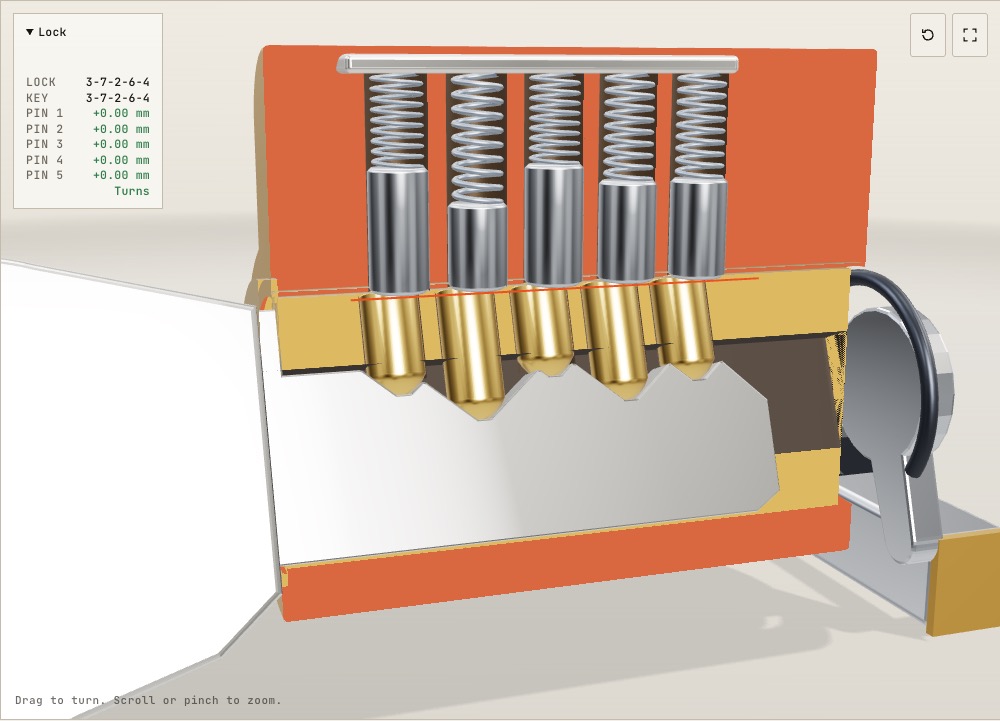
How does a pin tumbler lock work inside? A 3D cutaway
On a common Schlage key one cut depth differs from the next by 0.381 mm, and that small step is enough to keep a wrong key from turning.
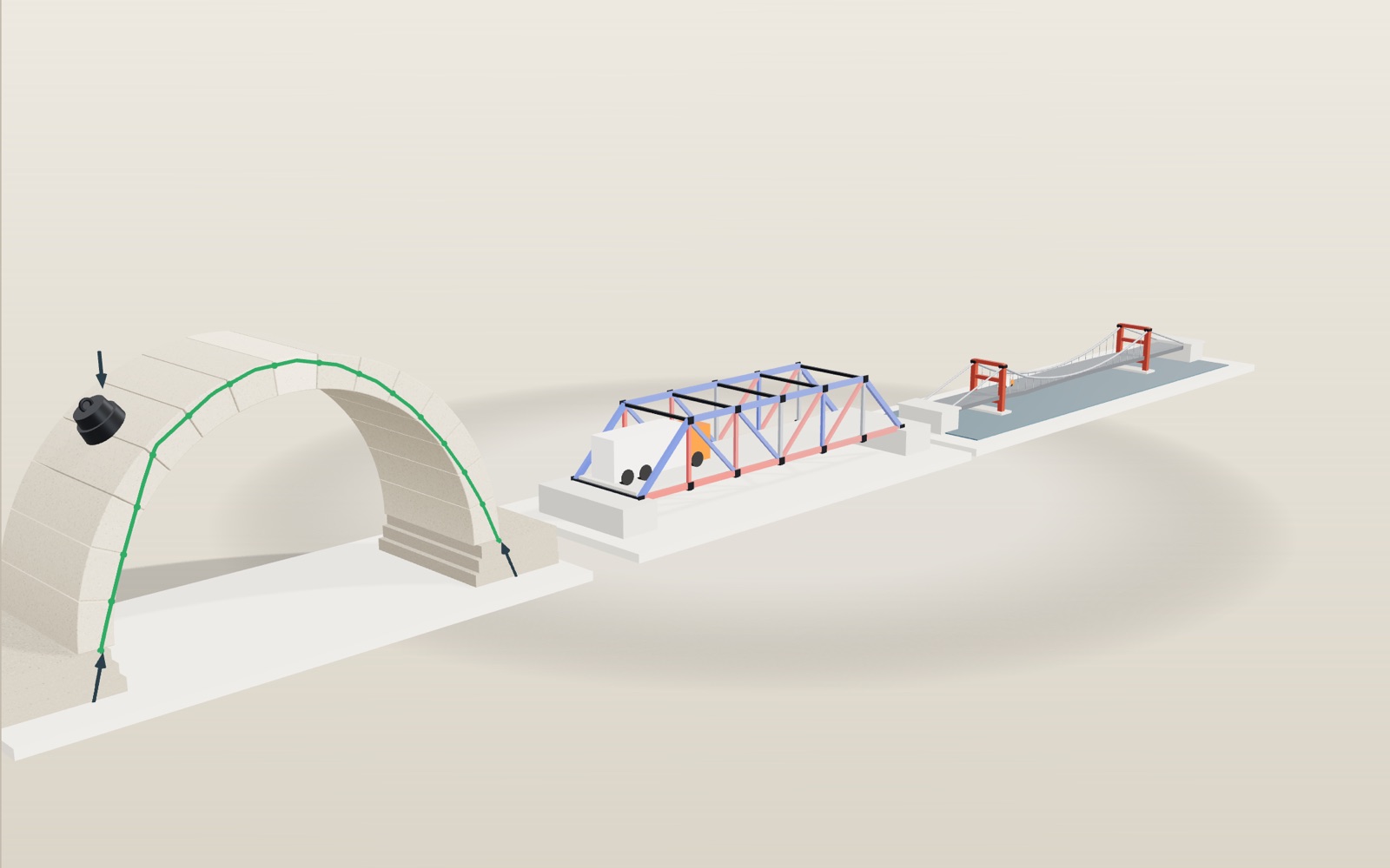
Stone arch bridge: load it and watch how it carries weight
A stone arch has no glue between its blocks, yet it stands on its own once the last stone is set at the top.
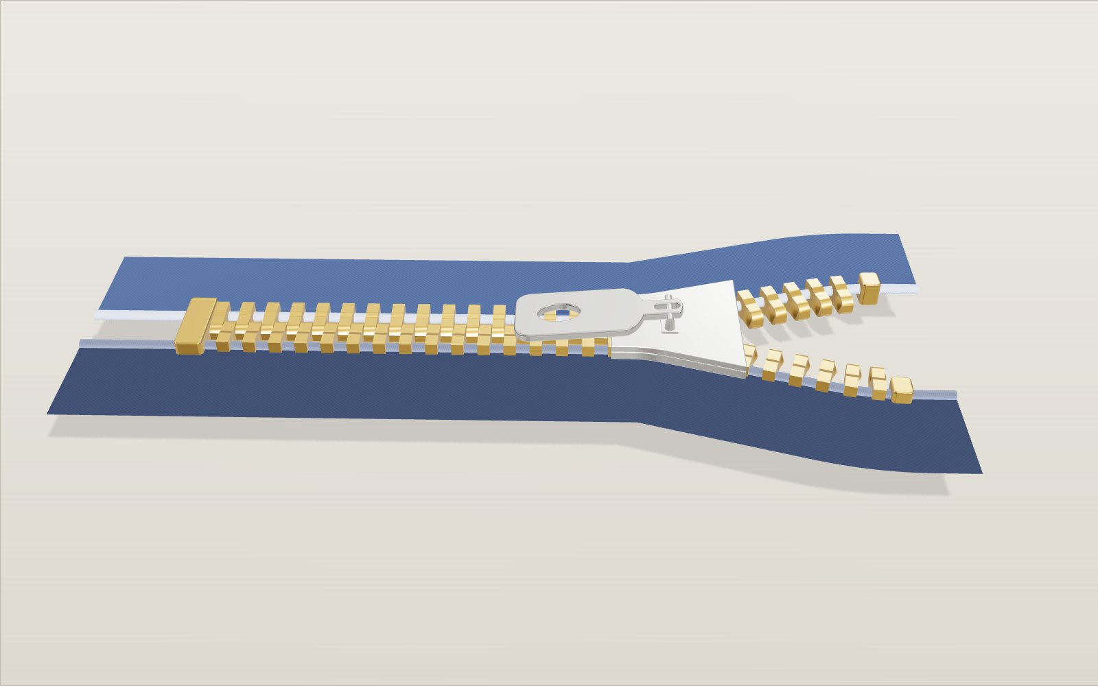
How a zipper works: how the slider locks the teeth
Nothing inside a zipper slider moves, yet the same Y-shaped channel locks the teeth on the way up and unlocks them on the way down.
Billiards angles: aiming, spin and the diamond system, step by step
Two equal balls that meet without spin part at a right angle, and a ball struck at its centre slides for 12/49 of v²/μg before it starts to roll.
Roller coaster physics: how roller coasters work
A train that creeps over a 42 m lift hill at 3 m/s is doing 99 km/h at the bottom, and nothing but gravity has pushed it.
How to do CPR, use an AED, help someone choking and use a fire extinguisher
Push 100 to 120 times a minute, about 5 cm deep: with a bystander doing that, survival in Korea in 2024 was 2.36 times higher.