Loading the model
This device cannot show the 3D model. You can read the guide steps below as text.
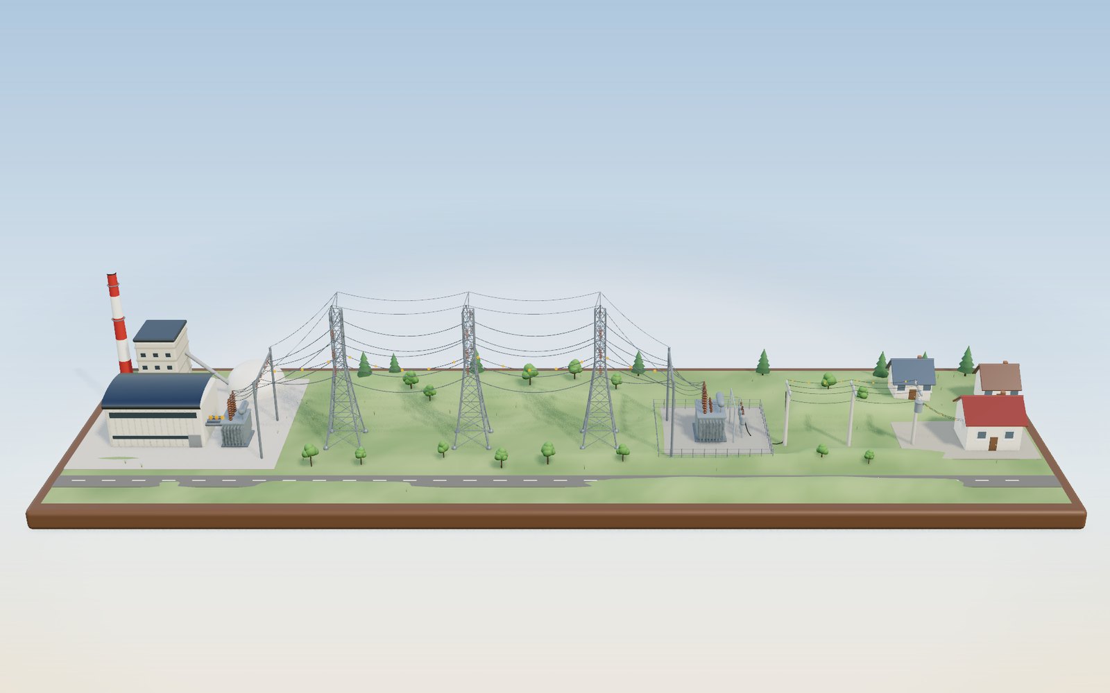
1 / 18 From a power station to your outlet Electricity made in the station on the left reaches the lamp in the house on the right almost at once. The tags show the voltage and current at each stage, and the orange beads show the current swinging back and forth, slowed 60 times. The buttons along the top open eight more scenes.
Drag to turn. Scroll or pinch to zoom.
Guide Parts Controls
01 From a power station to your outlet Electricity made in the station on the left reaches the lamp in the house on the right almost at once. The tags show the voltage and current at each stage, and the orange beads show the current swinging back and forth, slowed 60 times. The buttons along the top open eight more scenes.
02 The generator turns 3,600 times a minute Steam spins the turbine, and the generator on the same shaft turns with it. A two-pole generator has to turn 60 times a second to make 60 Hz. In the model it puts out 22 kV, so sending 500 MW takes about 13,100 amperes.
03 The step-up transformer raises the voltage Inside the tank the low-voltage coil has 5 thick turns and the high-voltage coil has 78 thin ones. Voltage rises by the turns ratio (22 kV to 345 kV is 1 : 15.7) and current falls by the same ratio. Move the voltage slider and the turns on the right-hand coil change with it.
04 Same power, lower voltage At 345 kV the 500 MW needs 837 A and loses 6.3 MW (1.26 %) in the 3-ohm line. The slider is now at 154 kV: the current is 1,875 A and the loss is 31.6 MW, five times more, so the wires run hotter and sag lower. At 22.9 kV the loss would be bigger than the power itself. A longer line or a thinner wire raises the resistance, and the loss with it.
05 The substation brings it down to 22.9 kV A transformer steps 345 kV down to 22.9 kV, and breakers send it out on many feeders. In Korea the path usually stops once more at 154 kV on the way; the model leaves that out. One feeder here carries 6.25 MW at about 158 A.
06 The pole transformer makes 220 V The three feeder wires are 22.9 kV apart from each other, but each is 13.2 kV from the neutral wire below. The can on the pole sits between one wire and the neutral and steps 13,200 V down to 220 V, a turns ratio of 60 : 1.
07 220 V at 60 Hz in the wall The voltage at the outlet swings between +311 V and −311 V 60 times a second, and 220 V is its effective (rms) value. Korean rules allow 198 to 242 V. The chart in the readout shows three cycles, 50 milliseconds.
08 When demand outruns supply, the frequency drops Demand has just jumped to 560 MW while the generator is still set to 500 MW. The missing power is taken from the spinning rotor, so it slows and the frequency dips to about 59.6 Hz. The governor opens up and the frequency settles at 59.825 Hz. Switch on AGC to bring it back to 60 Hz.
09 Some stations spin, some do not Coal, nuclear, gas and hydro stations turn heavy generators in step with the grid, and the steel wheels show how much energy each stores in its spin (the inertia constant H, in seconds). Wind, solar and batteries connect through inverters and add none. Raise the inverter share and the frequency falls faster after a unit is lost.
10 A summer day Demand is lowest before dawn and highest in the afternoon. Korea’s record is 97.1 GW, set on 20 August 2024. With 30 GW of solar the midday columns turn partly yellow, and the steepest climb moves to the hours around sunset.
11 The duck curve On a mild spring day with 60 GW of solar, the demand left for other plants sags at midday and climbs steeply after sunset. California’s grid operator called this shape a duck. Gas and hydro have to cover that evening rise within a few hours.
12 A unit trips A 1,400 MW unit has just dropped off an 80 GW grid. For the first seconds only the spinning mass of every machine holds the frequency; then governors add reserve, and in the model the frequency bottoms out near 59.67 Hz about 8 seconds later. Add batteries to keep it above 59.8 Hz.
13 Inside the transformer The core is stacked from thin steel sheets so that eddy currents stay small. Each limb carries a low-voltage coil inside a high-voltage one, all under oil that carries the heat to the radiators. In the model a 1,000 MVA unit at 80 % load wastes about 3.1 MW, an efficiency of about 99.6 %.
14 Insulators, bundles and sag A 345 kV string of 20 glass discs holds the wire 2.9 m from the steel. Four wires per phase keep the surface field near 10 kV/cm, well under the 21.6 kV/cm at which corona starts in fair weather. Warm the wire to 80 °C and the 400 m span sags from 10.5 m to about 13.6 m.
15 765 kV in the rain At 765 kV the string has 40 discs, 5.8 m long. Rain lowers the corona onset to about 14.5 kV/cm, and even six wires per phase give 15 kV/cm, so the wet line glows and crackles. That is why very high voltage lines carry big bundles and still hum in wet weather.
16 Direct current under the sea Jeju’s first link has carried 180 kV DC from Haenam since 1998. An AC cable that long would spend much of its rating charging its own capacitance; in this model a 154 kV AC cable fills up at about 150 km. Over land, DC pays from about 700 km here because of the cost of the converter stations.
17 One fault, then another A fault takes out the Inland to City line. Its power moves onto the other paths, the Inland to Dam line runs over its limit, and about 18 seconds later its protection trips it. Then the next line goes. Press Shed 10 % in time, as operators do, and the cascade stops.
18 The panel in your home Every branch has its own breaker. Switch on the kettle, microwave, rice cooker and air fryer together and the 20 A kitchen breaker trips after a while. The residual-current breaker compares the current going out with the current coming back and trips at 30 mA. Press its yellow test button: it should drop at once.
Power station Turbine hall, boiler house and stack. Switch on See inside to look at the turbine and generator. Turbine and generator Steam turbine and generator on one shaft. The red marks show it turning, 60 times slower than a real two-pole machine at 3,600 rpm. Step-up transformer Oil-filled tank with cooling fins. Low-voltage bushings on the side, tall high-voltage bushings on top. Core and windings Five thick turns on one leg of the iron core, many thin turns on the other. The ratio of turns sets the voltage. 345 kV tower Steel lattice carrying two circuits of three phases, with two ground wires on top to take lightning strikes. Insulator strings Chains of porcelain discs that hold the wires away from the steel. Higher voltage needs a longer chain. Conductors Aluminium wires with a steel core. In the model they glow and sag lower as the I²R heat goes up. Substation transformer Brings 345 kV down to 22.9 kV for the distribution feeders. Breakers and bus Breakers open a feeder within a fraction of a second when there is a fault. 22.9 kV feeder Three phase wires on the crossarm and a neutral wire below them, on concrete poles. Pole transformer Connected between one phase and the neutral: 13.2 kV in, 220 V out. House and meter The service drop from the pole comes in at the meter on the wall. Outlet Two round holes with earth clips at the side. 220 V at 60 Hz. Coal power station Boiler house, turbine hall, a banded stack and a covered coal store. Its steam turbine adds a large spinning mass. Nuclear power station Domed containment building beside the turbine hall. It runs near full output almost all the time. Gas combined cycle Two gas turbines whose hot exhaust raises steam in the boilers behind them, and an LNG tank. Quick to start. Hydro power station Arch dam, lake, two penstocks and the powerhouse at the foot of the dam. Wind farm Three turbines. The rotors turn, but the generators reach the grid through inverters, so the grid feels no spinning mass. Solar farm Rows of tilted panels on frames and an inverter. No moving parts. Battery storage Containers of lithium-ion cells with power converters. They answer in a fraction of a second. Hourly demand 24 columns, one per hour. Blue: demand the dispatcher must meet. Yellow on top: what solar supplies. Supply level A green glass sheet at the height of the supply from nuclear, coal, hydro, other plants and the gas switched on. City Its windows light up after sunset as demand moves to homes. Frequency meter Needle on a 58 to 62 Hz dial. Green is the normal band, 59.8 to 60.2 Hz; red is below 59.0 Hz, where load shedding starts in the model. Generators in service Turbine-generator sets that stay on. Their rotors hold the frequency for the first seconds, then their governors add output from the reserve. The unit that trips A 1,400 MW set, about one large nuclear unit (model value). Press Trip a unit and it drops off the grid. Battery for frequency Glows green while it discharges. In the model it reaches full output in about 0.2 s. Load blocks Three groups of buildings. Each under-frequency stage (59.0, 58.8 and 58.6 Hz) switches one group off. Laminated core Three limbs and two yokes stacked from thin steel sheets, stepped so the cross-section is nearly round. The magnetic flux runs round it. Low-voltage winding The inner coil: a few turns of thick copper carrying the large current. High-voltage winding The outer coil, a stack of discs with many turns of thinner copper and paper insulation between them. Tank and conservator The steel tank, cut open at the front, and the conservator above it that gives the oil room to expand as it warms. Insulating oil Mineral oil fills the tank. It insulates the windings and carries their heat to the radiators. Radiators Thin panels on both sides. Warm oil sinks through them as it cools. Bushings Porcelain columns that bring the conductors out through the lid: tall ones for high voltage, short ones for low. Tap changer Switches between taps on the winding to trim the output voltage by a few per cent. Tower and crossarm Galvanised steel lattice. The crossarm holds one phase well away from the tower body. Insulator string Glass discs in a chain, about 146 mm each. The model uses 10 for 154 kV, 20 for 345 kV and 40 for 765 kV. Conductor bundle Several wires per phase held 45 cm apart by spacers (model). More wires lower the field at each wire surface. Corona When the field at the wire surface passes the breakdown strength of air, the air glows violet, crackles and wastes power. Converter stations Valve halls at each end turn AC into DC and back. An AC switchyard stands on one side and a DC smoothing reactor on the other. Valves Stacks of semiconductor valve modules inside the halls. Switch on See inside to look through the walls. Submarine cable Copper conductor, paper insulation, lead sheath and steel armour, laid on the seabed. The cut piece shows the layers. Island Wind turbines and a town. With a two-way link the island can import at night and send surplus wind power out. Power stations Coast (3,000 MW), Inland (2,000 MW) and the dam (1,000 MW). When the grid splits, the stations in each piece share the load they can reach. Towns Five towns and an industrial area. Their windows dim in proportion to the load that cannot be served. Transmission lines Twelve lines coloured by loading. Click one to trip it. Power splits over parallel paths in inverse proportion to their reactance (DC power flow). Panel box A metal box in the wall with a door. In a real home the inside stays behind a cover. Bus bars Copper bar feeding every breaker, the blue neutral bar and the green-yellow earth bar. Breakers Main breaker (40 A in the model), residual-current breaker with a yellow test button, and five branch breakers. Click a tripped lever to switch it back on. Wiring and earth Branch cables up to the rooms and the earth wire down to a copper rod in the ground. Appliances Click one to switch it on or off. A green light shows it is getting power.