Loading the model
This device cannot show the 3D model. You can read the guide steps below as text.
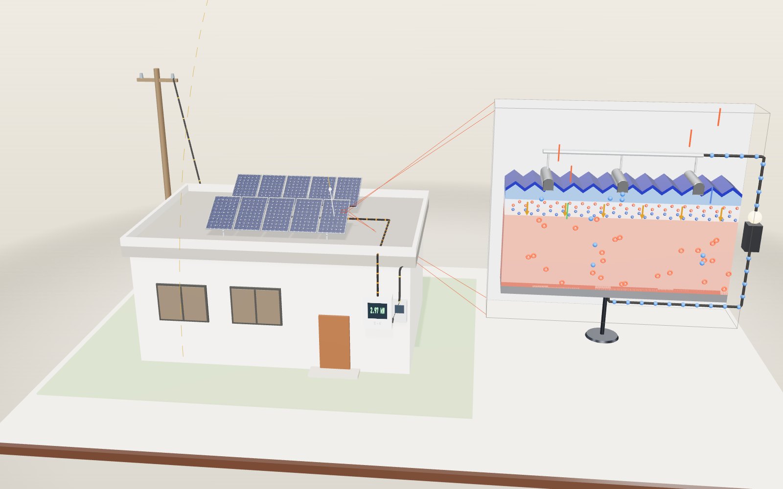
1 / 11 A 3 kW roof at noon Ten panels sit on two racks tilted 30°, and the sun is 60° above the southern horizon, so the light meets them square on. The array makes 3.07 kW of direct current. On the right is a slice through one cell, drawn many thousands of times larger.
Drag to turn. Scroll or pinch to zoom.
Guide Parts Controls
01 A 3 kW roof at noon Ten panels sit on two racks tilted 30°, and the sun is 60° above the southern horizon, so the light meets them square on. The array makes 3.07 kW of direct current. On the right is a slice through one cell, drawn many thousands of times larger.
02 60 cells under glass The panel on the right is lifted apart. Under the glass lie 60 cells wired in series, then a white backsheet. Behind it hangs the junction box with three bypass diodes, one for every 20 cells. At 25 °C the model panel gives 307 W, which is 18.8 % of the sunlight on it.
03 Why the cells look dark blue Bare silicon reflects about a third of the light. The top is etched into small pyramids, so a ray that bounces off one face often hits the next, and a 75 nm film of silicon nitride cancels much of the rest by interference. What little comes back is blue.
04 Where n-type meets p-type The thin top layer has spare electrons (n-type) and the thick base has missing electrons, called holes (p-type). Where they meet, electrons and holes cancel and leave behind fixed ions. Those ions set up an electric field pointing from the n side to the p side.
05 Light knocks electrons loose A photon with more than 1.12 eV of energy can free an electron and leave a hole. If the pair reaches the junction, the field pulls the electron up into the n layer and pushes the hole down. Electrons then run along the wire, through the load, and meet the holes at the back.
06 The angle of the sun A winter noon in Seoul: the sun is only 29° high. With the panels tilted 33°, the rays arrive 28° away from straight on and the light on each panel is 737 W/m². Drag the tilt to 0° and it falls to 442 W/m², because a flat panel catches the same beam spread over a larger area.
07 Heat and a single leaf At 65 °C the cells lose about 0.4 % of their power for every degree above 25 °C. A leaf now covers one cell. That cell can no longer carry the string current, so the bypass diode for its group of 20 switches on and the panel falls to 167 W. Without the diode, the shaded cell would be heating at 138 W.
08 From the roof to the kettle The inverter on the wall turns the direct current into 220 V alternating current and finds the voltage at which the array gives the most power. At noon the array delivers 2.97 kW after a 3 % inverter loss. The house uses 0.5 kW and the rest goes out through the meter to the grid.
09 More than one peak A leaf now covers 60 % of one cell, and the panel's power curve is no longer a single hill: the shaded cell limits the current on the right, and on the left its bypass diode has switched on. A perturb-and-observe tracker starts near open-circuit voltage, climbs the first peak it meets and stops at about 151 W. The highest peak, at 21.6 V, gives 200 W. Press Full sweep to find it.
10 The real sun over Seoul 21 December in Seoul, 12:00 on the clock. The NOAA equations put the sun 28.6° above the horizon and 8° east of due south, because solar noon in Seoul comes at 12:30. On a clear day one panel tilted 33° makes 1.36 kWh, and the ten panels give 13.2 kWh after the inverter. A 62° tilt would catch the most that day: 1.55 kWh per panel.
11 Six ways to build a cell The slice now shows a TOPCon cell: an n-type wafer with a boron emitter on top, and at the back an oxide a nanometre or two thick under doped polysilicon. Because the wafer is n-type, holes go to the front fingers and electrons to the back. In the NLR efficiency table the best TOPCon cell reached 26.68 % in December 2025. The Cell sections tab has PERC, heterojunction, back-contact and perovskite-on-silicon cells too.
Solar module Toughened glass on top, an aluminium frame and a white backsheet underneath. Inside are 60 cells, about 1.65 m × 0.99 m in all. Silicon cells 60 cells 156.75 mm square, joined in series by thin ribbons. In the model each makes about 5.1 W at 0.55 V in full sun. Junction box and bypass diodes Three diodes on the back, one for each group of 20 cells. When a cell in a group is shaded, its diode lets the current go round. Anti-reflection coating A film of silicon nitride about 75 nm thick on a surface etched into tiny pyramids. It is the reason cells look dark blue. n-type silicon A thin top layer doped with phosphorus, which gives it spare electrons. The electrons collected by the fingers come through here. pn junction and depletion region Where n meets p, fixed positive ions (red) face fixed negative ions (blue). The orange arrows show the electric field between them. p-type silicon The thick base, doped with boron, which leaves holes. Most of the light is absorbed here. Electrodes Silver fingers on the front and an aluminium layer on the back. They collect the charges and pass them to the wire. Photons, electrons and holes Coloured streaks are photons. Each one absorbed makes a blue electron and a red hole. Blue light stops near the top; red goes deeper. Inverter Turns the direct current from the roof into alternating current for the house and keeps the panels at their maximum power point. Meter and house The house uses what it needs. In the model it draws 0.5 kW and the rest goes out through the meter to the street.