Loading the model
This device cannot show the 3D model. You can read the guide steps below as text.
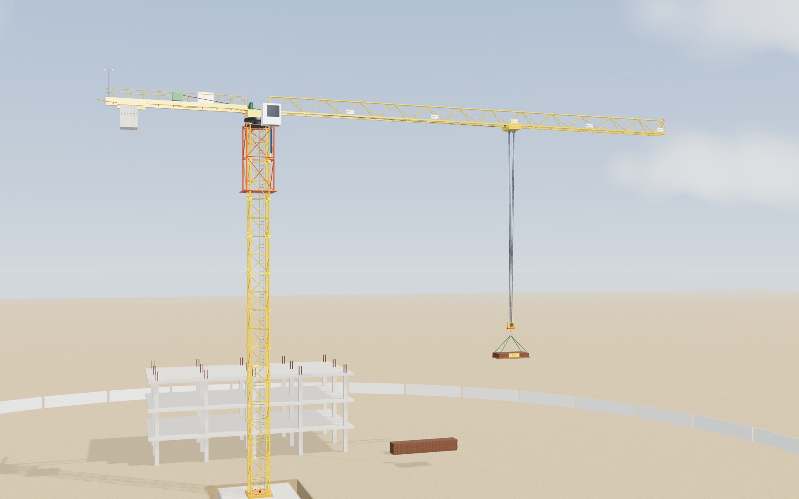
1 / 11 A crane on a building site The crane stands on a concrete pad next to a building going up. It lifts 3 t at 30 m. The panel in the corner shows the load moment, the rated limit at this radius and where the weight of the whole crane meets the foundation.
Drag to turn. Scroll or pinch to zoom.
Guide Parts Controls
01 A crane on a building site The crane stands on a concrete pad next to a building going up. It lifts 3 t at 30 m. The panel in the corner shows the load moment, the rated limit at this radius and where the weight of the whole crane meets the foundation.
02 Weight times distance What the crane feels is not the weight alone but the weight times its distance from the mast axis. 2 t at 40 m makes 80 t·m, the same as 8 t at 10 m. Move the trolley and watch the number in the red tag.
03 The load chart The rated moment of this model crane is 160 t·m, and the hoist may lift at most 8 t. So the crane takes 8 t out to 20 m, then 160 ÷ r: 4 t at 40 m and 3.2 t at the tip. The curve in the corner is that chart, and 4 t at 40 m sits right on it.
04 The counterweight pulls the other way Six 3 t blocks hang 13 m behind the axis and make 234 t·m the other way. Add the jib's own 198 t·m, the counter-jib's 40 t·m, 80 t·m from 4 t at 20 m and 12 t·m from the hook block, and the mast is left with only 16 t·m. Take the blocks off and it becomes 250 t·m.
05 Where the weight meets the ground Pad, mast, jib, blocks and load weigh 298 t together. With 3.2 t at the tip their resultant passes 0.38 m from the centre of the pad, well inside the middle third, which ends 1.33 m out, and far from the edge at 4 m.
06 Past the limit 5 t at 40 m is 200 t·m, 125% of the rating. The lamp turns red and a real limiter would refuse to lift or run the trolley out. The mast bends elastically by about 18 cm at the top. Here the bend is drawn ten times larger so you can see it.
07 When the wind is too strong Korean safety rules stop erecting and dismantling above gusts of 10 m/s and stop operation above 15 m/s. At 18 m/s the load is set down, the trolley is parked and the slewing brake is released. The wind then turns the jib downwind like a weathervane.
08 The crane raises itself A new section waits on the monorail. With a second section on the hook at 24.5 m, the crane is balanced. The cylinder lifts the upper part 4 m, the section rolls into the gap and is bolted, and the mast is one section taller.
09 A real load chart This is the Liebherr 172 EC-B 8 with its 62.5 m jib, as printed in the manufacturer's data sheet. It lifts 8 t up to 16.5 m and 1.60 t at the tip. At 60 m it may lift 1.70 t, so 1.6 t is 94%. The rated moment falls from 132 t·m near the mast to 100 t·m at the tip, so the real curve drops faster than the model's.
10 Same rule, another top A luffing crane tilts its jib instead of running a trolley. On the Liebherr 357 HC-L with two falls it lifts 24 t up to 18 m. At 40 m it may lift 9.07 t, so 8 t is 88%. Out of service it stands its jib up at 75°, which keeps it clear of the buildings around it.
11 The load is a pendulum The load hangs on about 23 m of rope, so it swings with a period near 9.6 s. Starting and stopping the trolley sets it swinging. Operators start and stop gently, and some crane controls damp the swing for them.
Foundation A reinforced concrete pad 8 m square and 1.5 m deep, 230 t in the model. The mast is bolted to anchors cast into it. The dashed square on top is its middle third. Mast Ten lattice sections, each 2 m square, 4 m tall and 2.5 t (model values). It carries the weight of everything above it and resists the bending that any unbalanced moment puts into it. Climbing frame A cage that slides on the outside of the mast, with a hydraulic cylinder pushing on lugs on the mast. It lifts the whole upper part by one section so a new section can slide in. Slewing unit A large ball-bearing ring with gear teeth and two slewing motors. Everything above it turns; everything below stays put. Out of service its brake is released so the jib can turn with the wind. Cab and limiter The operator sits here. The load moment limiter reads the hook load and the trolley radius, warns at 90% of the rated moment and stops lifting and outward trolley travel beyond 100%. The lamp on the roof shows its state. Jib A 50 m triangular lattice arm, 9 t, with its centre of mass 22 m from the axis (model values). Its own weight already makes 198 t·m about the mast before anything is hung from it. Trolley Runs along the bottom chords of the jib on four wheels and carries the sheaves for the hoist rope. Its distance from the mast axis is the radius in every load chart. Hook block Hangs on four falls of hoist rope. Together with the trolley it weighs 0.6 t in the model, which counts in the moments but not in the rated load. Counter-jib A 15 m platform on the other side of the axis with the hoist winch and its motor. Its 5 t at 8 m pull back with 40 t·m. Counterweight Concrete blocks of 3 t each, hung 13 m behind the axis. Six of them make 234 t·m against the jib and the load. The number is set by the manufacturer for each jib length. Anemometer Three cups on a mast at the highest point of the crane measure the wind where the crane feels it, which is usually stronger than at ground level. Load A pallet of rebar bundles. Its mass is set with the Load slider. For wind it is treated as a flat face of 8 m² (model value).