FIG. 61How It Works
Why a tower crane doesn't tip over
A tower crane that lifts 8 tonnes next to its mast may carry only 3.2 tonnes at the tip of its 50 m jib, and the reason is a single multiplication.
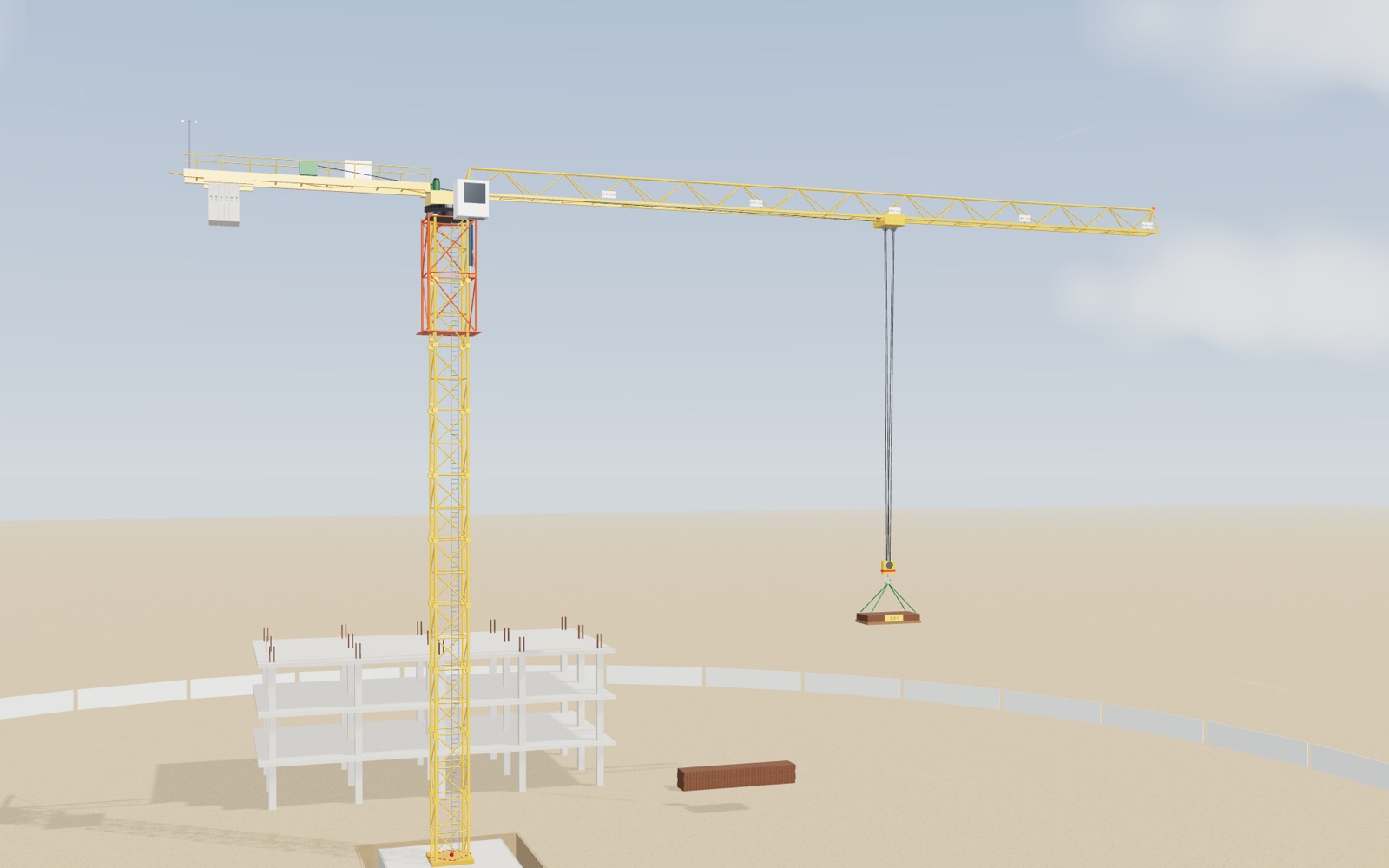
This device cannot show the 3D model. You can read the guide steps below as text.
1 / 11 A crane on a building siteThe crane stands on a concrete pad next to a building going up. It lifts 3 t at 30 m. The panel in the corner shows the load moment, the rated limit at this radius and where the weight of the whole crane meets the foundation.
Drag to turn. Scroll or pinch to zoom.
What the model shows
Look up at a building site and the tower crane seems to break a simple rule. A steel arm fifty metres long sticks out to one side of a thin lattice tower, a bundle of steel hangs from the far end, and nothing falls over. The answer is not that the crane is heavy, although it is. The answer is that the crane keeps track of one number all day, and refuses to let it grow past a limit.
The model is a flat-top tower crane of a common size class: a 40 m mast of ten lattice sections on a concrete pad, a 50 m jib with a trolley, and a 15 m counter-jib with the hoist winch and six concrete counterweight blocks. None of it copies one manufacturer's data sheet. Every dimension and mass is a model value, chosen to be in the right range and to keep the arithmetic easy to follow. You can move the trolley, change the load, take blocks off the counterweight, turn the crane, raise the wind and run the climbing sequence. The panel in the corner of the stage recalculates everything each time.
Weight times distance is what the crane feels
Hold a full bag of shopping close to your chest and it feels light. Hold the same bag at arm's length and your shoulder starts to complain within seconds. The weight has not changed. What changed is the distance between the weight and the joint that has to hold it.
A crane works the same way. What matters at the mast is the load moment: the load multiplied by its horizontal distance from the mast axis, which crane people call the radius. In the model, 2 t at 40 m gives 2 × 40 = 80 tonne-metres (t·m), exactly the same as 8 t at 10 m. Both try to bend the mast and tip the crane by the same amount. That is why the trolley position matters as much as the weight on the hook, and why the red tag on the stage always shows the product rather than the weight alone.
Reading a load chart
Every tower crane carries a load chart, and the operator is expected to know it. The model crane has two limits. The hoist, its rope and the hook block may lift at most 8 t anywhere. The structure may carry a load moment of at most 160 t·m. Close to the mast the first limit governs; further out, the second one does. The two meet at 160 ÷ 8 = 20 m.
| Radius | Rated load | Load moment |
|---|---|---|
| 3 to 20 m | 8.00 t | up to 160 t·m |
| 25 m | 6.40 t | 160 t·m |
| 30 m | 5.33 t | 160 t·m |
| 35 m | 4.57 t | 160 t·m |
| 40 m | 4.00 t | 160 t·m |
| 45 m | 3.56 t | 160 t·m |
| 50 m | 3.20 t | 160 t·m |
The curve in the corner of the stage is this table drawn as a graph, with the forbidden area shaded. The dot is where you are. Move the trolley out with a load on the hook and the dot slides along under the curve until it touches it. Real charts are not perfect hyperbolas. They usually fall a little faster at long radius, because the weight of the jib itself grows with its length, and each jib length has its own chart. The shape is the same, though: flat near the mast, then falling.
The counterweight answers the jib
Before anything is hung on the hook, the jib already pulls on the mast. In the model it weighs 9 t with its centre of mass 22 m out, which makes 9 × 22 = 198 t·m. The counter-jib on the other side, 5 t at 8 m, pulls back with 40 t·m. Six 3 t blocks hung 13 m behind the axis pull back with 6 × 3 × 13 = 234 t·m.
Add them up with the hook block (0.6 t together with the trolley) and an empty crane with its trolley pulled in to 3 m leans backward with 74.2 t·m. With the rated 3.2 t at the tip it leans forward with 114 t·m. The mast has to take anything between those two numbers. Without the blocks, the same lift would put 348 t·m into it, all in one direction.
So the counterweight does not have to cancel the load. It moves the middle of the working range. That is also why more is not better. With eight blocks instead of six, the empty crane leans back with 152 t·m, and backward stability becomes the problem. The US rule for tower cranes names backward stability as a hazard that the person directing erection must address, and it requires the amount and position of counterweight to be exactly what the manufacturer or a registered engineer specifies. Try it with the Counterweight blocks slider and watch the moment at the mast axis change sign.
Where all the weight meets the ground
A tower crane does not stand on its mast. It stands on its foundation. The model uses a reinforced concrete pad 8 m square and 1.5 m deep, which at 2.4 t per cubic metre weighs 230.4 t. Add the mast, the upper part, the counterweight and a 3.2 t load and the total comes to 298.2 t.
All of that weight acts like one force, the resultant, and the question is where it passes through the pad. With the rated load at the tip, the net moment of 114 t·m pushes the resultant 114 ÷ 298.2 = 0.38 m from the centre, toward the jib. The small plan in the corner of the stage shows that point, and a red dot marks it on top of the pad.
Two lines matter. The first is the middle third of the pad, the dashed diamond, which reaches 8 ÷ 6 = 1.33 m from the centre along each axis. As long as the resultant stays inside it, the whole underside of the pad keeps pressing on the soil. At 0.38 m the pressure is 5.99 t/m² under the front edge and 3.32 t/m² under the back edge. The second line is the edge of the pad, 4 m out. Only there would the crane start to tip, and getting the resultant there with 3.2 t on the hook would need 4 × 298.2 = 1,193 t·m, almost seven and a half times the rated moment. In the model, the steel of the jib and mast would be far beyond its design load long before the pad could roll. The limit in the cab protects the steel and the foundation together.
What the limiter does at 90 and 100 percent
Nobody expects an operator to multiply in their head. A tower crane carries a load moment limiter: it weighs the load on the hook, knows where the trolley is, and compares the product with the chart. US rules require tower cranes to have a device that prevents moment overloading, a trolley travel limiting device at both ends of the jib, and a display of the load on the hook. Korean rules require overload protection devices on cranes to be adjusted so they work, and forbid loading a crane beyond its rated load.
The model limiter warns at 90% of the rated value and turns the lamp on the cab red above 100%. A real limiter would then stop the two motions that make things worse: hoisting up and running the trolley out. Lowering and bringing the trolley in stay possible, because they reduce the moment. The model lets you push past the limit so you can see the numbers. Set 5 t at 40 m and you get 200 t·m, 125% of the rating. Press Play and the trolley runs out until the limiter would stop it, then comes back.
The mast is not perfectly rigid either. With the rated load at the tip, its top moves about 14 cm and leans by 0.40°, and the deflection disappears again when the load comes off. That is far too small to see at full scale, so the Show bending ×10 switch draws it ten times larger. Nothing else in the model is exaggerated.
Wind: why the crane stops at 15 m/s and then lets go
Wind loads a crane in three ways. It pushes on the mast, it pushes on the side of the jib, and it swings the load. Wind pressure grows with the square of the speed, q = ½ρv². At 10 m/s it is 62.5 Pa, at 15 m/s it is 141 Pa, and at 30 m/s it is 563 Pa, nine times more than at 10 m/s.
Korean safety rules set two limits in gust speed. Above 10 m/s, erecting, repairing, inspecting and dismantling a tower crane must stop. Above 15 m/s, operating it must stop. After a gust above 30 m/s, every part of an outdoor crane has to be checked before work starts again. US rules leave the number to the manufacturer for erecting and climbing. The anemometer on top of the crane is there because wind at 40 m is usually stronger than at the gate.
What the crane does next looks strange at first. The operator sets the load down, parks the trolley where the manufacturer says, and releases the slewing brake. The crane is then free to turn, and the wind turns it, like a weathervane, until the jib points downwind. The reason is the side area. The jib is long and catches the wind far from the axis, so it always ends up on the downwind side. In the model at 30 m/s, a jib held across the wind takes 184 t·m of overturning moment and 470 kN·m of turning moment on the slewing ring. Pointing downwind, it takes 55 t·m and no turning moment at all. The Health and Safety Executive in Northern Ireland issued an alert in 2014 after three luffing jib cranes collapsed in high winds. It reminded users that an unattended crane must be left in free slew, at the correct out-of-service radius.
How the mast grows one section at a time
A crane that builds a tower has to grow with it. It does not need a second crane for that. A climbing frame slides over the outside of the mast just below the slewing unit, and a hydraulic cylinder on one side pushes on lugs fixed to the mast.
The sequence in the model follows the usual order. First the crane lifts a new 4 m section and sets it on the monorail of the climbing frame. Next it balances itself. With a second 2.5 t section on the hook, the moment at the axis is zero when the trolley stands at 76 ÷ 3.1 = 24.5 m, so the cylinder pushes straight up and nothing bends. The bolts between the slewing unit and the mast come out, and the cylinder lifts the whole upper part by 4 m. The new section rolls into the gap and is bolted at both ends. Finally the cylinder retracts and takes hold one section higher. The mast is now 44 m. During all of this the crane must not slew, and the climbing slider shows the balance radius. Korean rules also require a tower crane taller than its free-standing height to be tied to the building's walls, which is why tall cranes have collars at intervals.
A worked lift: a 4.5 t precast panel
Say the site needs a 4.5 t wall panel set on the third floor, and the panel has to be placed 30 m from the mast. This is an assumed job, not data from a real site. The question is the one the operator and the lift planner ask before every heavy pick: does the chart allow it, and how close to the edge is it?
The hoist limit is not the issue, since 4.5 t is below 8 t. The moment is: 4.5 × 30 = 135 t·m. The chart allows 160, so the panel uses 135 ÷ 160 = 84% of the rating. At 30 m the rated load is 5.33 t, so there is 0.83 t to spare. The limiter stays quiet because it only warns from 90%.
Now turn the question around and ask how far out the panel can go. The limit is 160 ÷ 4.5 = 35.6 m. The warning starts earlier, at 0.9 × 160 ÷ 4.5 = 32.0 m. If the panel has to land at 40 m, then 4.5 × 40 = 180 t·m, which is 112.5% of the rating, and the limiter will not let the trolley go that far. The planner then has three options: move the crane base closer, split the load so each piece is 4 t or less at 40 m, or bring in a larger crane. Raising the limit is not one of them.
The mast feels more than the load alone. The same 4.5 t at 30 m, together with the jib, counter-jib, six blocks and the 0.6 t hook block, leaves a net 77 t·m forward at the mast axis. That moves the resultant on the foundation 77 ÷ 299.5 = 0.26 m from the centre. The rating is a statement about the structure, and the foundation sees the whole sum.
One more detail: the rated load in the chart does not include the hook block, but the moment on the mast does. Stand at 30 m and watch the 4.5 t load in the model: the red tag shows 135 t·m, while the net moment at the axis shows 77 t·m after the counterweight. These are two different numbers answering two different questions.
Sliding the counterweight window
The counterweight does not change how much the mast swings between an empty crane and a full one. It changes where that swing sits. In the model the mast moment goes from the empty crane with the trolley at 3 m to the 3.2 t load at 50 m, and that span is 188.2 t·m for every block count. Each 3 t block pulls back 39 t·m and shifts the whole span by that much. The values below come straight from the model and are positive when the crane leans toward the jib.
| Blocks | Empty, trolley at 3 m | 3.2 t at 50 m |
|---|---|---|
| 0 | +159.8 t·m | +348.0 t·m |
| 2 | +81.8 t·m | +270.0 t·m |
| 4 | +3.8 t·m | +192.0 t·m |
| 5 | −35.2 t·m | +153.0 t·m |
| 6 | −74.2 t·m | +114.0 t·m |
| 7 | −113.2 t·m | +75.0 t·m |
| 8 | −152.2 t·m | +36.0 t·m |
With four blocks the empty crane is almost perfectly balanced, and the loaded crane carries 192 t·m forward. With six the two ends are −74 and +114. The peak size is smallest at seven blocks (113.2), but only by a hair compared with six (114), so the model does not recommend seven. The reasons are partly outside this model: a real jib and counter-jib are designed for a specific counterweight, the backward lean has its own limit, and the counterweight is fixed by the manufacturer for each jib length. The table shows the shape of the decision, not a number to copy.
Check the foundation for the extreme case. With eight blocks and the empty crane at 3 m, the net backward moment is 152.2 t·m on a total weight of 301 t. The resultant sits 152.2 ÷ 301 = 0.51 m behind the centre, still inside the 1.33 m middle third. The pad is not what fails first. The mast and slewing ring are loaded in a direction they were not sized for.
Kinds of tower crane
The crane in the model is a flat-top tower crane: a horizontal jib with a trolley, a counter-jib behind it, and the whole upper part turning on top of the mast. Liebherr, the manufacturer that describes its first mobile tower crane in the history section above, sorts its range into fast-erecting cranes and top-slewing cranes, and lists flat-top, high-top, heavy-load, luffing and derrick versions among the top-slewing ones.
| Type | How the radius changes | What it is good at |
|---|---|---|
| Flat-top | A trolley runs along a horizontal jib with no tower above it | Simple load chart, cranes can work close above each other |
| Hammerhead | A trolley runs along a jib held up by tie bars from a cat-head tower | Long jibs and heavy loads, Liebherr's high-top EC-H series |
| Luffing jib | The jib tilts up and down about a hinge | Crowded sites, where a long horizontal jib could sweep neighbouring buildings or cranes |
| Fast-erecting | Usually a trolley jib again, on a tower built to go up quickly | Jobs where quick set-up matters; Liebherr lists these as a separate class from top-slewing cranes |
| Mobile or crawler | The boom is raised or lengthened on wheels or tracks | Moving between sites, no tower and no foundation pad of this kind |
The load moment rule is the same in all of them. What changes is how the radius is made. On a luffing crane the radius is the jib length times the cosine of its angle above horizontal. With an assumed 50 m jib, a 37° angle gives about 40 m, and a 60° angle gives 25 m. Raising the jib brings the load closer in and lets the crane lift more, the same way pulling the trolley in does on the model.
The luffing layout has its own risks. In January 2007 a luffing tower crane in Liverpool was lifting a light load close to its minimum radius, in wind near the in-service limit. According to the review by Tim Watson, wind from the front held the jib up and made the luffing rope go slack, and the jib fell backwards across the site and killed one worker. The Health and Safety Executive for Northern Ireland, writing in 2014 about three luffing crane collapses in high winds, stressed that such cranes must be parked at the correct out-of-service radius with the slew brake released. Parked at too small a radius, a crane may not be able to turn freely, and the alert also tells users to check that nearby buildings or other cranes do not stop it from slewing.
Reading a real load chart: the Liebherr 172 EC-B 8
The model crane's chart is one clean shape, 8 t out to 20 m and then 160 t·m divided by the radius. A manufacturer's chart is a table, and the one on the stage is copied row by row from Liebherr's published data sheet for the 172 EC-B 8 Litronic, a flat-top crane. The sheet lists one row for each jib length, from 24.4 m to 62.5 m, and gives the rated load at fixed radii along that row. It also says that the values hold up to 50 m of hoisting height, because a longer hoist rope weighs more and that weight counts against the load.
With the longest jib, 62.5 m, the crane may lift its full 8 t out to 16.5 m. At 30 m the sheet gives 4.11 t, at 40 m 2.90 t, at 50 m 2.18 t and at the tip 1.60 t. Between two printed radii the stage draws a straight line and marks the value as interpolated. That straight line is a reading aid on this page, not a method taken from the sheet.
The same sheet shows why the counterweight depends on the jib. The 62.5 m jib needs 17.5 t of counterweight blocks, the 50 m jib 13.75 t, the 40 m jib 12.15 t and the 30 m jib 9.65 t. A shorter jib weighs less and pulls less on the front of the crane, so less concrete is needed at the back. This is the real version of the counterweight slider on the stage, and it is why rules ask for exactly the amount the manufacturer gives rather than as much as possible.
Why the rated moment is not one number
In the model the product of load and radius stays at 160 t·m everywhere beyond 20 m. On the 172 EC-B 8 it does not. With the 62.5 m jib, 8 t at 16.5 m makes 132 t·m, 4.11 t at 30 m makes 123 t·m, 2.90 t at 40 m makes 116 t·m, and 1.60 t at 62.5 m makes only 100 t·m. The blue line in the load chart panel shows this fall.
One likely part of the reason is the jib itself. The farther out the trolley runs, the more of the jib hangs beyond the point where the load acts, and the steel has to carry its own weight on a longer arm at the same time as the load. The trolley and hook block also count, and the manufacturer has checked the structure, the mast and the slewing ring at every radius, not only the overturning balance. The sheet does not say which check governs at each radius, so the stage does not claim one. The result is plain, though: a constant moment curve drawn from the corner of a real chart would promise more at the tip than the crane is rated for.
The shorter jibs on the same sheet behave in a similar way. With the 50 m jib the full 8 t is allowed out to 21.5 m, and just beyond the corner, at 22 m, the sheet gives 7.82 t, which is exactly 8 t × 21.5 ÷ 22. Further out the values fall away from that constant moment again, to 3.05 t at 50 m.
For cranes in the catalogue that publish only the largest load and the load at the largest radius, the stage draws an estimate: the tip value times the largest radius, divided by the radius, capped at the largest load. Because real charts fall faster than that toward the tip and slower near the mast, the estimate is marked as such and is only there to show the size of the numbers.
Flat top, hammerhead and luffing jib side by side
The type buttons rebuild the top of the same crane three ways. A flat-top crane, like the model, has no structure above the jib: the jib and the counter-jib are trusses stiff enough to carry themselves. Several flat-top cranes can work on one site with their jibs passing close above and below each other.
A hammerhead has a short tower, the cat-head, above the slewing unit. Tie bars run from its top to points along the jib and to the end of the counter-jib, so the jib works more like a beam hung from above. Liebherr's large hammerhead series is the EC-H, which it calls high-top. On its product page the 1000 EC-H 50 Litronic lifts 50 t and still 11 t at its 80 m radius, and the 1188 EC-H 40 Fibre reaches 90 m.
A luffing-jib crane has no trolley. The jib is hinged at its foot and the hook hangs from the tip, and the radius is set by raising or lowering the jib. In the model the hinge is 3 m ahead of the mast axis and the jib is 59 m long, so 15° above horizontal gives 60 m of radius and 75° gives about 18.3 m. Liebherr's data sheet for the 357 HC-L 12/24 with a 60 m boom gives 24 t up to 18 m when the hook is reeved with two falls, 9.07 t at 40 m and 3.20 t at 60 m, and the stage uses that table whenever the luffing type is chosen.
The difference matters most when the crane is left alone. A flat-top or hammerhead crane out of service has its slew brake released and turns with the wind, and its whole jib sweeps a circle. A luffing crane first raises its jib to an out-of-service angle. The same 357 HC-L sheet gives 75° and a minimum reach of 18.5 m for the 60 m boom, and the Liebherr luffing brochure gives out-of-service radii from 9.6 m for the 195 HC-LH to 15.5 m for the 710 HC-L. On a city site surrounded by buildings, or with several cranes close together, that small circle is often the reason to choose a luffer.
Wind on the load, not only on the crane
The Korean rule on the stage stops operation above gusts of 15 m/s. Other rule sets put the line elsewhere. The Construction Plant-hire Association in the UK explains that tower cranes built to EN 14439 are designed for an in-service wind of 20 m/s, and that UK industry takes tower cranes out of service at 16.5 m/s, 38 mph, so that there is still time to put the crane into its out-of-service position before the wind gets stronger. As a rule of thumb, the same guidance notes that wind can rise from 13 m/s to 20 m/s in about 20 minutes. The wind panel switches between these three limits.
The crane's limit already includes some wind on the load. The allowance the CPA describes is about 1 m² of area for each tonne of load. A large, light load gets its own, lower limit, and the CPA gives a worked example that the stage repeats: a formwork panel 3.6 m by 2.4 m weighing 1.3 t. Its area of 8.64 m² times a drag coefficient of 1.2 gives 10.4 m² of wind area, eight times the allowance. The permissible speed is the crane's limit times the square root of 1.2 × 1.3 ÷ 10.4, which is 0.39. With a crane limit of 17 m/s that gives 6.6 m/s, which the CPA rounds to 6.5 m/s. With the Korean 15 m/s it is 5.8 m/s. Above that speed the stage sets the panel down, while the crane itself could keep working with a compact load. A vacuum lifter can bring the limit down further, and the CPA mentions 8 m/s for one.
Out of service, a parked tower crane still has to survive storms. The CPA's note on out-of-service wind speeds explains that cranes to EN 14439 are designed for reference storm speeds from a European map, 24 m/s in regions A and B, 28 m/s in region C, 32 m/s in D and 36 m/s in E, and that most are supplied for region C. After a storm, the Korean rule on the stage asks for an inspection of every part once the gusts have exceeded 30 m/s, and the CPA guidance asks that a crane stays out of service until the wind has been below the limit for at least 10 minutes.
The load is a pendulum
The load hangs on a rope from the trolley, so it behaves like a pendulum. For a small swing its period is 2π times the square root of the rope length divided by g. With the model's 23 m of rope that is 9.6 s, and with 3 m less rope it is 9.0 s. The period does not depend on the mass of the load.
When the trolley speeds up, the load lags behind; when the trolley stops, the load swings on. On the stage the trolley accelerates gently, as a real one does, but the swing still reaches a metre or more after an ordinary start and stop. The swing panel lets you drive the trolley by hand. The trick that works is to time the stop: if the trolley starts braking exactly one swing period after it started speeding up, the swing from braking cancels the swing from starting, and the load arrives almost still. The check script finds a residual swing of under 0.1 m for that case and over 2 m when the button is held for 5 s instead.
Crane makers build this kind of timing into the control. Liebherr lists a wind force moment control and oscillation damping system among the assistance systems of its Litronic cranes, alongside a fine positioning mode and a function called Load Plus that raises the rated load by up to 20% for individual lifts.
Signallers and hand signals
The operator in the cab often cannot see where the load is going to land. A signaller on the ground or on the building watches the load and tells the operator what to do, by radio or by hand. The hand signals are standardised so that nobody has to guess. In Europe they come from the safety signs directive, and the UK regulations of 1996 print them in full: start, stop and end of the operation, raise and lower, move forwards and backwards, right and left, horizontal and vertical distance, and the emergency stop.
The wording is precise. Raise is the right arm pointing upwards with the palm facing forward, slowly making a circle. Lower is the right arm pointing downwards with the palm facing inwards, slowly making a circle. Stop is the right arm pointing upwards with the palm facing forwards, and danger, the emergency stop, is both arms pointing upwards with the palms facing forwards. The same text says that the signaller should do nothing else while directing the crane and should wear something that makes them easy to recognise. The signal panel uses those descriptions as cards; the stage moves the crane when the meaning is right.
Where the catalogue numbers come from
The 44 entries in the catalogue come from manufacturer pages and documents, checked on 27 October 2026. Liebherr's product pages give the largest load, the load at the largest radius, the largest radius and the highest free-standing hook height for its flat-top EC-B and high-top EC-H cranes, and for three of its luffers. Its luffing brochure adds the out-of-service radius, and its general tower crane brochure lists the heavy-load HC cranes, the fast-erecting K cranes and the 357 HC-L. Manitowoc's Potain pages give the same four numbers for the MDT and MCT topless cranes, the MR luffers and the MD cranes, though not every Potain entry has a hook height.
The numbers are copied as published and are not comparable in every respect. The largest load is usually reached only at a short radius with the hook reeved for heavy loads; the load at the largest radius belongs to the longest jib; the hook height is a free-standing value on one tower system. The tip moment in each entry is a simple product of two published numbers and is marked as calculated.
What the accident records show
Tower crane accidents are large when they happen, so people have counted them. The counts depend on who is counting, and none of them is a complete census.
Tim Watson Consulting collected 130 major tower crane accidents worldwide from 1989 to 2012 (collapses and serious structural damage on top-slewing and some self-erecting cranes, found in trade press and from the UK Health and Safety Executive). By the stage of the crane's life, about 35% happened in service, 11% out of service, and 41% while the crane was being erected (10%), dismantled (14%) or climbing (17%). The cause could be identified in only 46% of the cases, and the author notes that no single source holds accurate data. Those are small samples from public reports, and they show where to look, not a rate.
A Korean study of 260 tower crane accident reports filed with the Korea Occupational Safety and Health Agency between July 2012 and July 2020 found that lifting work accounted for 45.3% of the cases, falls were the most common type of accident at 35.8%, and the most frequent cause was a faulty work method, at 38.8%. A Korean government press release on 28 July 2022 gives one concrete case of the climbing stage: on 14 July a worker died after falling together with the telescoping cage while a tower crane was being raised.
These records line up with the model. The calm, in-service lifts that the load chart and the limiter protect are only part of the picture. Climbing, erecting and dismantling need the crane to be balanced at a specific radius, with specific bolts in place and nobody slewing, and this is where procedures matter most. It is also why the climbing slider in the model shows the balance radius rather than leaving it to the viewer.
Common misunderstandings
"A heavier counterweight makes the crane safer." Only up to the manufacturer's number. The empty crane then leans backward, as the table above shows, and rules require exactly the specified amount.
"The limit is where the crane tips over." The model crane's pad would need 1,193 t·m to start tipping, against 160 t·m of rated moment. The limit protects the steel structure and its connections and keeps a margin on stability.
"The limiter weighs the load." It needs two numbers, the load on the hook and the trolley radius. The same 3 t is fine at 30 m and over the limit at 55 m on a longer jib.
"A crane in free slew is loose and dangerous." It is the safe condition when nobody is operating. With the brake released, the crane turns downwind, and the model's turning load on the slewing ring goes from 470 kN·m (jib across a 30 m/s wind) to zero. A brake left on can leave the jib across the wind.
"The wind limit is about the average wind." The Korean rules use gust speed, meaning the instantaneous wind speed. A gust of 15 m/s at the top of a 40 m mast can arrive while the average wind is still well below that.
"The tower is fixed to the building." Only once it grows taller than its free-standing height; Korean rules then require ties to the structure. Below that, the foundation alone carries everything.
Try it on the screen
- Set Load to 4.5 and slide Trolley radius from 20 m to 40 m. The load moment reaches 90% of the rating near 32 m, and the cab lamp turns red above 35.6 m.
- Set Trolley radius to 3 m and Load to 0. Change Counterweight blocks from 8 down to 0 and watch the moment at the axis go from −152 t·m through zero near 4 blocks to +160 t·m.
- Set Trolley radius to 50 m, Load to 3.2 and Gust speed to 15. The load swings about 2.1° on its rope. At an assumed 20 m of rope that is 0.7 m sideways. At 30 m/s it swings 8.2°, about 2.9 m.
- Turn Slewing angle to 90° and 0° with a 30 m/s gust and Load at 0. The wind moment on the foundation is 55 t·m with the jib downwind and 184 t·m with the jib across.
- Switch on Show bending ×10 and compare the top of the mast with Load at 0 and at 5 t.
Where the model is simpler than a real crane
- The load chart is the simple shape min(8 t, 160 t·m ÷ r). Real charts depend on jib length and hoist reeving and come from the manufacturer.
- The masses and the foundation are model values. A real foundation is designed for its soil by the manufacturer or a registered engineer, and some cranes stand on piles or on a building's structure instead.
- Wind uses one pressure for the whole height and fixed force coefficients. Design codes increase the pressure with height and add gust factors.
- The mast bends as one elastic beam with fixed ends at the pad. The pad's own rotation on the soil is left out.
- Dynamic effects are left out: starting and stopping a hoist or a slew adds force on top of the static load.
A short history
Cranes built into towers are old. The Alter Krahnen on the Moselle at Trier, built in 1413, is a stone tower with treadwheels inside; the whole interior, roof and jibs included, turned on a central wooden post. The steel tower crane that could be moved from site to site came much later. In 1949 Hans Liebherr built the TK 10, which Liebherr describes as the first mobile tower crane. Today's flat-top cranes keep the same layout of mast, slewing unit, jib, counter-jib and counterweight that the model shows.
How the numbers were checked
All values on the stage come from one set of plain formulas, and they were recomputed by hand. The check covers the load chart rows, the moments of jib, counter-jib and blocks, the resultant offset against a separate sum of each weight times its lever arm about the pad edge, the pressures under the pad, the wind forces and turning moments, the balance radius for climbing, and the mast deflection against the textbook formulas M·H²/2EI, F·H³/3EI and w·H⁴/8EI computed by numerical integration.
Questions
Why can a tower crane lift more close to the mast than at the tip?
Because the crane is limited by load moment, which is weight times radius. In the model the limit is 160 t·m, so it may lift 8 t at 20 m but only 3.2 t at 50 m. Close to the mast another limit takes over, the 8 t the hoist may lift.
What is the counterweight for if it does not cancel the load?
It moves the middle of the working range. Without it, a full load at the tip would put 348 t·m into the mast. With six blocks the mast sees between 74 t·m backward when empty and 114 t·m forward when fully loaded.
Can you just add more counterweight to lift more?
No. With too much counterweight the empty crane leans backward, and the jib, mast and slewing ring are designed for one specific amount. Rules require exactly the counterweight that the manufacturer or a registered engineer specifies.
What happens if the operator tries to lift too much?
The load moment limiter warns first and then stops hoisting up and running the trolley out. The operator can still lower the load or bring the trolley in, which reduces the moment.
Why does a tower crane spin freely in a storm?
When the slewing brake is released, wind turns the long jib downwind like a weathervane. In the model at 30 m/s that cuts the overturning moment from wind from 184 t·m to 55 t·m and removes the twisting load on the slewing ring.
At what wind speed does a tower crane stop?
In Korea, operation must stop in gusts above 15 m/s, and erecting, repairing, inspecting or dismantling must stop above 10 m/s. Elsewhere the limit usually comes from the manufacturer's manual. After gusts above 30 m/s, Korean rules require an inspection before use.
How does a tower crane get taller?
A hydraulic climbing frame lifts the whole upper part by one mast section while the crane is balanced, a new section slides into the gap and is bolted in, and the frame takes hold again one section higher.
How do I check whether a lift is allowed on the load chart?
Multiply the load by the radius and compare the result with the rated moment, then check the load against the hoist limit. In the model, 4.5 t at 30 m is 135 t·m, which is 84% of 160 t·m. At 40 m the same panel would be 180 t·m, 112.5%, and the limiter would stop the trolley at 35.6 m.
Why does the number of counterweight blocks matter if the load changes all the time?
Because the swing between an empty crane and a full one is fixed by the jib and the load chart, and the counterweight decides where that swing sits. In the model it is 188.2 t·m wide for every block count. With six blocks it runs from 74 t·m backward to 114 t·m forward, with eight from 152 backward to 36 forward.
How far does wind swing the load?
In the model, a 3.2 t load plus the 0.6 t hook block, with 8 m² facing the wind, swings about 2.1° at 15 m/s and 8.2° at 30 m/s. On an assumed 20 m of rope that is 0.7 m and 2.9 m sideways. A bigger or flatter load catches more wind.
When do tower crane accidents most often happen?
Two public data sets agree that the quiet in-service lift is not the whole story. In a review of 130 major accidents worldwide from 1989 to 2012, about 41% happened during erection, dismantling or climbing. In a Korean study of 260 reports from 2012 to 2020, lifting work was 45.3% of the cases and faulty work methods the most frequent cause at 38.8%.
What is a luffing jib crane?
A tower crane whose jib tilts up and down about a hinge instead of staying horizontal with a trolley. The radius is the jib length times the cosine of its angle, so raising the jib brings the load closer in. The load moment rule is the same as for the flat-top in the model.
What is the difference between a hammerhead and a flat-top tower crane?
Both have a horizontal jib with a trolley. A hammerhead has a short tower, the cat-head, above the slewing unit, with tie bars that hold up the jib and the counter-jib. A flat-top has nothing above the jib; its jib and counter-jib are stiff enough on their own. Flat-tops can work closer above one another on a crowded site, and hammerheads are common for the largest loads and longest jibs.
Why does a real load chart drop faster at the tip than load times radius would suggest?
Because the rated moment is not constant. On the Liebherr 172 EC-B 8 with a 62.5 m jib it is 132 t·m at 16.5 m and only 100 t·m at the 62.5 m tip, where the crane may lift 1.60 t. The manufacturer checks the steel structure, the mast and the slewing ring at every radius, and far out the jib's own weight takes more of the margin.
At what wind speed should a large panel no longer be lifted?
Lower than the crane's own limit. UK guidance takes a crane allowance of about 1 m² of area per tonne and reduces the limit by the square root of the ratio. For a 3.6 m by 2.4 m formwork panel weighing 1.3 t, with a drag coefficient of 1.2, the limit falls to 0.39 of the crane's: 6.5 m/s in the guidance's example with a 17 m/s crane.
Terms
- Radius: the horizontal distance from the mast axis to the hook.
- Load moment: load multiplied by radius, in tonne-metres (t·m).
- Rated load: the largest load allowed at a given radius, taken from the load chart.
- Load chart: the table or curve of rated load against radius for one crane configuration.
- Load moment limiter: the device that compares the actual load moment with the chart and stops unsafe motions.
- Jib: the long horizontal arm that carries the trolley.
- Counter-jib: the shorter arm on the other side that carries the winch and counterweight.
- Trolley: the carriage that runs along the jib and carries the hook block.
- Slewing: turning the upper part of the crane about the mast axis.
- Free slew (weathervaning): leaving the slewing brake released so the wind can turn the jib.
- Middle third: the central zone of a pad; while the resultant stays inside it, the whole underside presses on the soil.
- Climbing: raising a tower crane by inserting mast sections with a hydraulic climbing frame.
Sources
- Korea Ministry of Government Legislation, National Law Information Center, Occupational Safety and Health Standards Rules (산업안전보건기준에 관한 규칙), Article 37 (work stops above 10 m/s and 15 m/s gusts). https://www.law.go.kr/LSW//lsSideInfoP.do?lsiSeq=273603&joNo=0037&joBrNo=00&docCls=jo&urlMode=lsScJoRltInfoR (checked 2026-10-16)
- Same rules, Article 134 (adjustment of overload protection and other safety devices on cranes). https://www.law.go.kr/LSW//lsSideInfoP.do?lsiSeq=273603&joNo=0134&joBrNo=00&docCls=jo&urlMode=lsScJoRltInfoR (checked 2026-10-16)
- Same rules, Article 135 (no load beyond the rated load). https://www.law.go.kr/LSW//lsSideInfoP.do?lsiSeq=273603&joNo=0135&joBrNo=00&docCls=jo&urlMode=lsScJoRltInfoR (checked 2026-10-16)
- Same rules, Article 142 (tower cranes above free-standing height tied to walls). https://www.law.go.kr/LSW//lsSideInfoP.do?lsiSeq=273603&joNo=0142&joBrNo=00&docCls=jo&urlMode=lsScJoRltInfoR (checked 2026-10-16)
- Same rules, Article 143 (inspection after gusts above 30 m/s). https://www.law.go.kr/LSW//lsSideInfoP.do?lsiSeq=273603&joNo=0143&joBrNo=00&docCls=jo&urlMode=lsScJoRltInfoR (checked 2026-10-16)
- US Code of Federal Regulations, 29 CFR 1926.1435, Tower cranes (wind speed for erecting and climbing, plumb tolerance 1:500, counterweight, backward stability, load moment limiting and trolley travel limiting devices), eCFR. https://www.ecfr.gov/current/title-29/subtitle-B/chapter-XVII/part-1926/subpart-CC/section-1926.1435 (checked 2026-10-16)
- Same section, Legal Information Institute, Cornell Law School. https://www.law.cornell.edu/cfr/text/29/1926.1435 (checked 2026-10-16)
- Health and Safety Executive for Northern Ireland, Preventing catastrophic failure of luffing jib tower cranes in high winds (2014). https://www.hseni.gov.uk/alert/preventing-catastrophic-failure-luffing-jib-tower-cranes-high-winds (checked 2026-10-16)
- City of Trier, Alter Krahnen (stone harbour crane built in 1413 by the boatman Gobel; treadwheels inside, the whole interior with the roof turned 360 degrees on a central wooden post), 2024. https://www.trier.de/leben-in-trier/stadtportrait/geschichte/kulturdenkmaeler/11854.Alter-Krahnen.html (checked 2026-10-17)
- Liebherr, First mobile tower crane from Liebherr turns 70, press release, 19 August 2019 (TK 10, patent for the mobile tower crane issued 19 August 1949). https://www.liebherr.com/en-us/n/first-mobile-tower-crane-from-liebherr-turns-70-25428-3782185 (checked 2026-10-17)
- HyperPhysics, Georgia State University, Torque. http://hyperphysics.phy-astr.gsu.edu/hbase/torq.html (checked 2026-10-16)
- NASA Glenn Research Center, The Drag Equation (force from ½ρv²). https://www.grc.nasa.gov/www/k-12/airplane/drageq.html (checked 2026-10-16)
- NASA Glenn Research Center, Center of Gravity. https://www.grc.nasa.gov/www/k-12/airplane/cg.html (checked 2026-10-16)
- Met Office, Beaufort wind force scale (wind speeds in m/s). https://www.metoffice.gov.uk/weather/guides/coast-and-sea/beaufort-scale (checked 2026-10-17)
- MIT course 1.105, Deflections due to Bending, chapter 10 of Engineering Mechanics notes (end-loaded cantilever tip deflection PL³/3EI). https://web.mit.edu/1.105/emech10_04.pdf (checked 2026-10-17)
- Tim Watson Consulting, A Review of Recent Tower Crane Accidents and the Lessons Learned (130 major accidents worldwide 1989 to 2012; Liverpool luffing crane, January 2007), presentation at the KHL International Tower Crane Conference, 2012. https://www.khl-group.com/events/itc/assets/tim-watson.pdf (checked 2026-10-22)
- Son, Kim et al., Study to Secure the Safety of Tower Cranes through Disaster Case Analysis at Construction Sites (건설현장의 재해사례 분석을 통한 타워크레인 안전성 확보 방안 연구), Journal of the Korean Institute of Building Construction 22(1), 2022 (260 cases filed with the Korea Occupational Safety and Health Agency, July 2012 to July 2020). https://www.kci.go.kr/kciportal/ci/sereArticleSearch/ciSereArtiView.kci?sereArticleSearchBean.artiId=ART002810823 (checked 2026-10-22)
- Korea Ministry of Employment and Labor, press release of 28 July 2022 on machinery and equipment fatalities at large construction sites (tower crane climbing fall on 14 July 2022). https://www.moel.go.kr/common/downloadFile.do?bbs_id=12&bbs_seq=13791&file_ext=pdf&file_seq=20220702313 (checked 2026-10-22)
- Liebherr, Tower Cranes product overview (fast-erecting, top-slewing, flat-top, high-top, heavy-load, luffing and derrick classes). https://www.liebherr.com/en/int/products/construction-machines/tower-cranes/tower-cranes.html (checked 2026-10-22)
- Liebherr, 172 EC-B 8 Litronic, FEM technical data (radius and capacity charts LM 1 and LM 2 for jibs from 24.4 m to 62.5 m, counterweight for each jib length, capacities valid up to 50 m hoisting height). https://assets-cdn.liebherr.com/versions/3157b929-cffe-4a72-a13e-39ab6ca7ad5e/original/ (checked 2026-10-27)
- Liebherr, Flat-top EC-B product range (maximum hook height, maximum lifting capacity, maximum radius and capacity at maximum radius for each model), pages 1 and 2. https://www.liebherr.com/en-us/tower-cranes/products/top-slewing-cranes/flat-top-ec-b/flat-top-ec-b-4355695 (checked 2026-10-27)
- Liebherr, High-top EC-H product range. https://www.liebherr.com/en-us/tower-cranes/products/top-slewing-cranes/high-top-ec-h-4355700 (checked 2026-10-27)
- Liebherr, Luffing HC-L product range and 280 HC-L 12/24 Litronic product page. https://www.liebherr.com/en-us/tower-cranes/products/top-slewing-cranes/luffing-hc-l-series-7500813 and https://www.liebherr.com/en-ca/p/82086-4020303 (checked 2026-10-27)
- Liebherr, HC-LH and HC-L series brochure, 2025 (maximum load, jib head load, maximum radius and out-of-service position of each luffing crane). https://www-assets.liebherr.com/media/bu-media/lhbu-lbc/brochures/top-slewing-cranes/luffing-hc-l/liebherr-towercranes-hc-l-series-2025-en.pdf (checked 2026-10-27)
- Liebherr, Tower Cranes brochure (EC-B, EC-H, HC-L, HC and K tables; Load Plus up to 20%; wind force moment control and oscillation damping). https://www.liebherr.com/shared/media/construction-machinery/tower-cranes/brochures/tower-cranes/tower-cranes-en.pdf (checked 2026-10-27)
- Morrow Equipment, 357 HC-L 12/24 Litronic data sheet MEC-MKT-1317 (Liebherr radius and capacity tables for one and two falls, minimum radius out of operation). https://public.morrow.com/wp-content/uploads/2021/04/357-HC-L-12-24-Litronic.pdf (checked 2026-10-27)
- Manitowoc, Potain Top-Slewing cranes (maximum capacity, maximum radius, maximum tip capacity and hook height per base for each model). https://www.manitowoc.com/potain/top-slewing-cranes (checked 2026-10-27)
- Construction Plant-hire Association, Tower Crane Interest Group, TIN 020 The Effect of Wind on Tower Cranes In Service (20 m/s design limit, 16.5 m/s UK out-of-service practice). https://cpa.uk.net/wp-content/uploads/2025/04/CPA-TCIG-TIN-020-Issue-D-140819.pdf (checked 2026-10-27)
- Construction Plant-hire Association, TIN 110 Planning and Control of Lifting Operations in Wind, July 2025 (1 m² per tonne, formwork panel example, vacuum lifter 8 m/s, 10 minute rule). https://cpa.uk.net/wp-content/uploads/2025/08/CPA-CIG_TCIG-TIN-110-Planning-Control-of-Lifting-Operations-in-Wind-V1-July-2025.pdf (checked 2026-10-27)
- Construction Plant-hire Association, TIN 027 Tower Crane Out-of-Service Wind Speeds (EN 14439, FEM 1.005, reference storm speeds by region). https://cpa.uk.net/wp-content/uploads/2025/04/CPA-TCIG-TIN-027-Issue-C-140701.pdf (checked 2026-10-27)
- The Health and Safety (Safety Signs and Signals) Regulations 1996, Schedule 1 Part IX, Minimum requirements for hand signals, legislation.gov.uk. https://www.legislation.gov.uk/uksi/1996/341/schedule/1/made (checked 2026-10-27)
- HyperPhysics, Georgia State University, Simple Pendulum (period 2π√(L/g)). http://hyperphysics.phy-astr.gsu.edu/hbase/pend.html (checked 2026-10-27)
- Calculations on this page: Q(r) = min(8 t, 160 t·m ÷ r), manufacturer charts interpolated on straight lines between printed radii, V = Vmax × √(1.2 m ÷ (Cw A)), T = 2π√(L/g), M = Σ mᵢxᵢ, e = M ÷ V, p = V ÷ B² × (1 ± 6e/B), q = ½ρv², F = q·C·A, r_balance = 76 ÷ (Q + 0.6), δ = M·H²/2EI + F·H³/3EI + w·H⁴/8EI. Worked examples, the block table and the swing values come from the same functions.
More exhibits
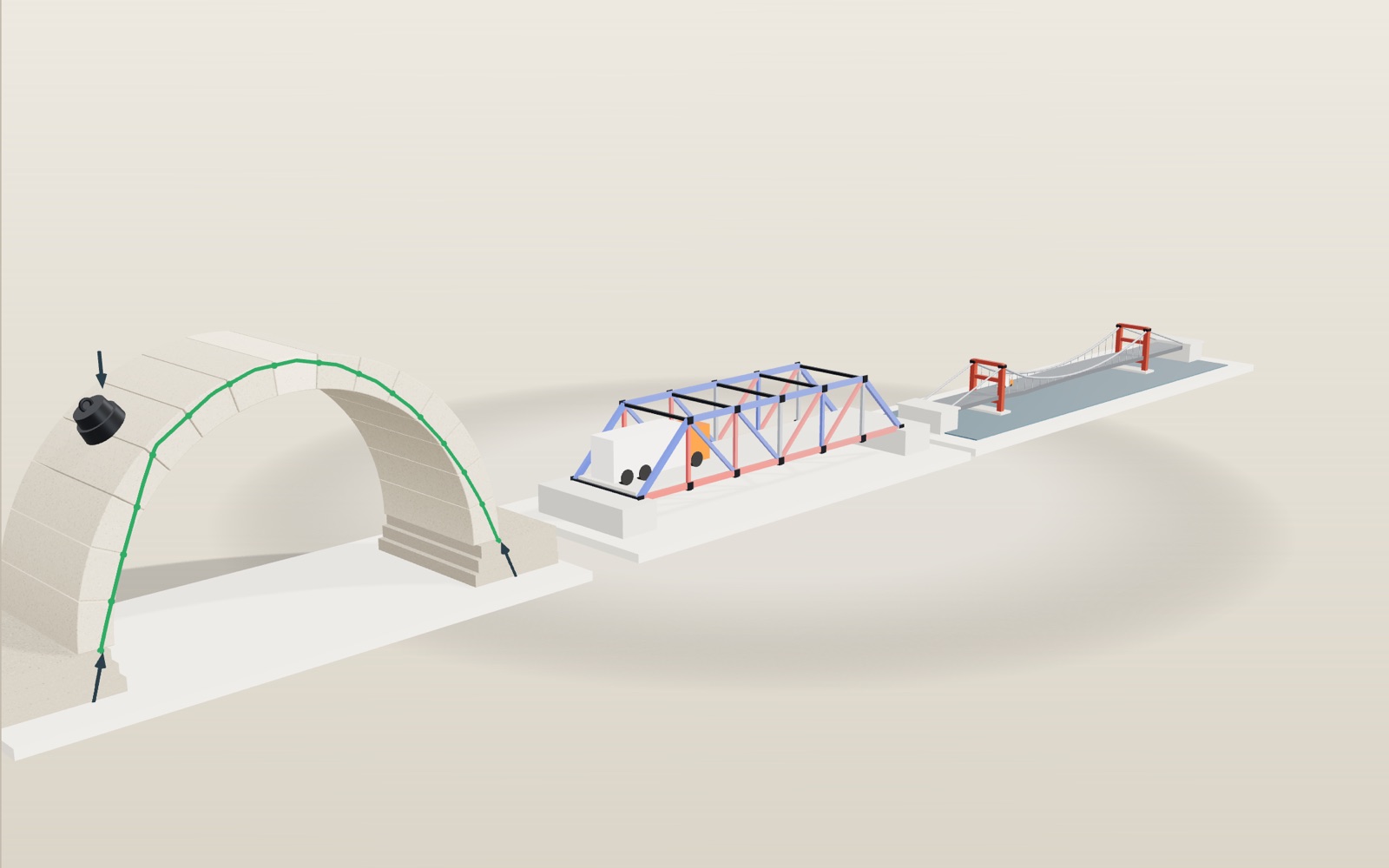
Stone arch bridge: load it and watch how it carries weight
A stone arch has no glue between its blocks, yet it stands on its own once the last stone is set at the top.
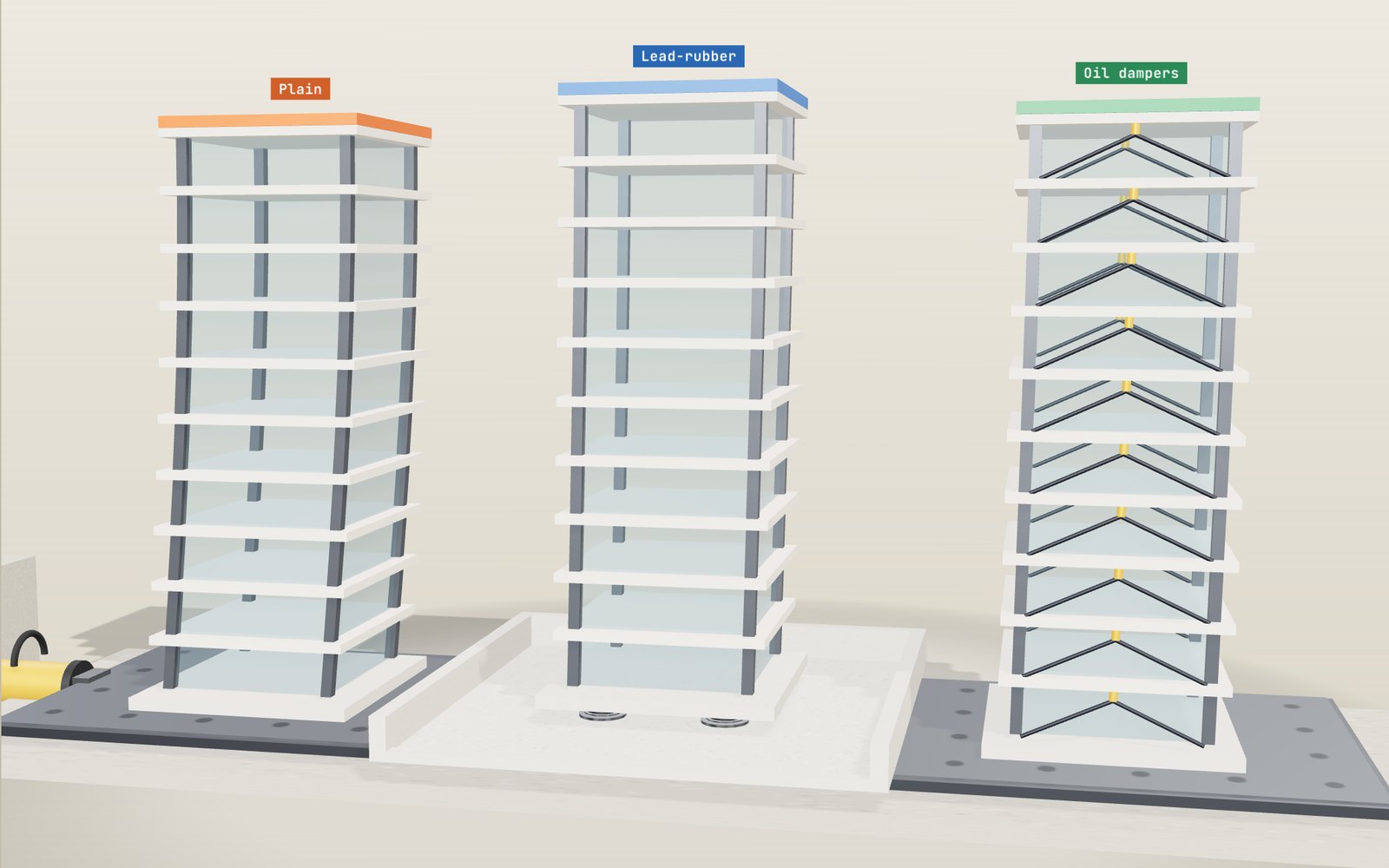
How buildings resist earthquakes
Shake a six-storey model at 0.6 seconds, its own period, and its floors bend about 14 times more than at one second. Rubber bearings, dampers and braces each answer that in a different way.
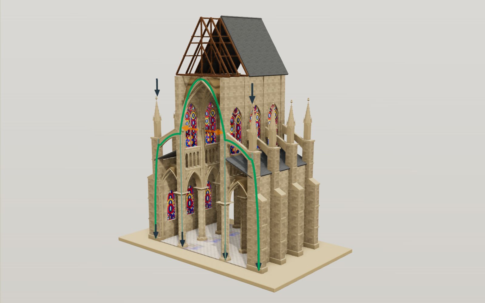
Gothic cathedral: flying buttresses, interactive model
The stone vault of Amiens Cathedral hangs 42.3 metres above the floor, and the walls under it are mostly glass.
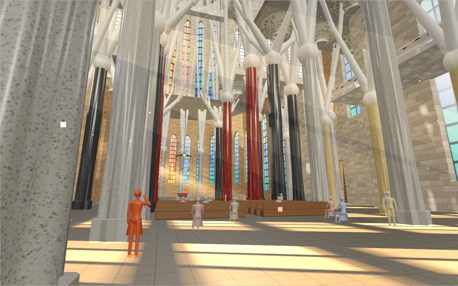
Walk through the Sagrada Família
Inside the Sagrada Família the columns branch like trees 45 m up, and the sun moves blue and orange light across the floor.
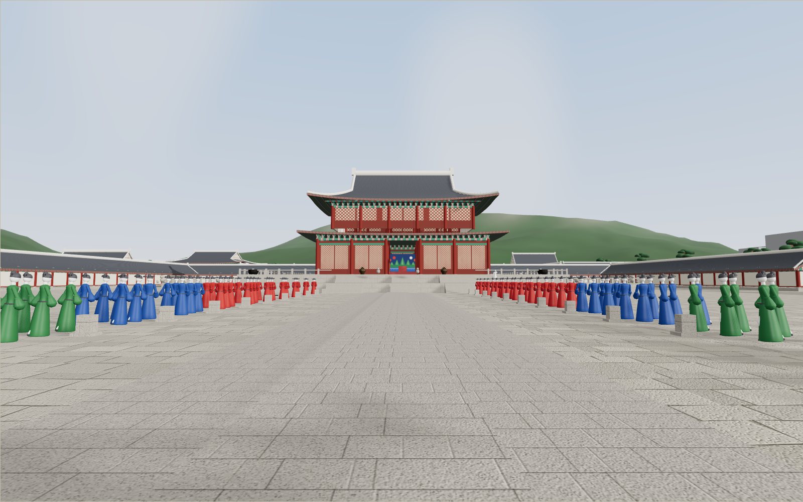
Walk through Gyeongbokgung Palace
In the courtyard of the throne hall, 24 stones told each official where to stand, from the first grade by the hall to the ninth by the gate.
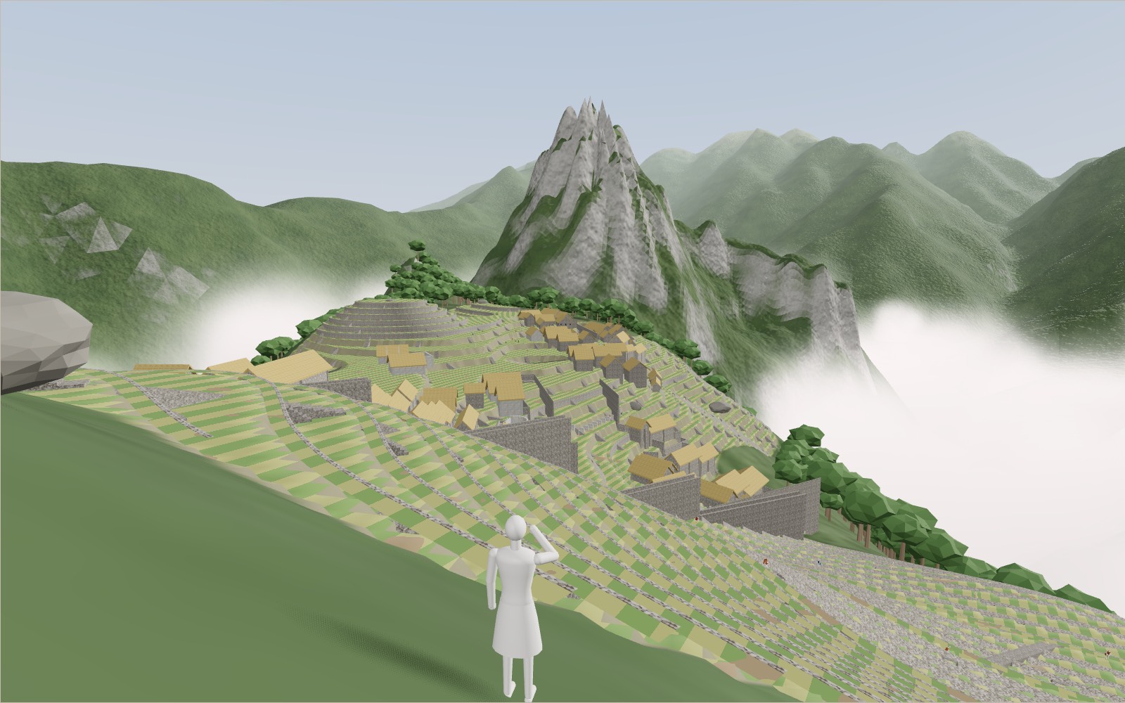
Walk through Machu Picchu
Most of the work that holds Machu Picchu on its ridge, 60 per cent by one estimate, lies under the ground in foundations and drains nobody sees.