Loading the model
This device cannot show the 3D model. You can read the guide steps below as text.
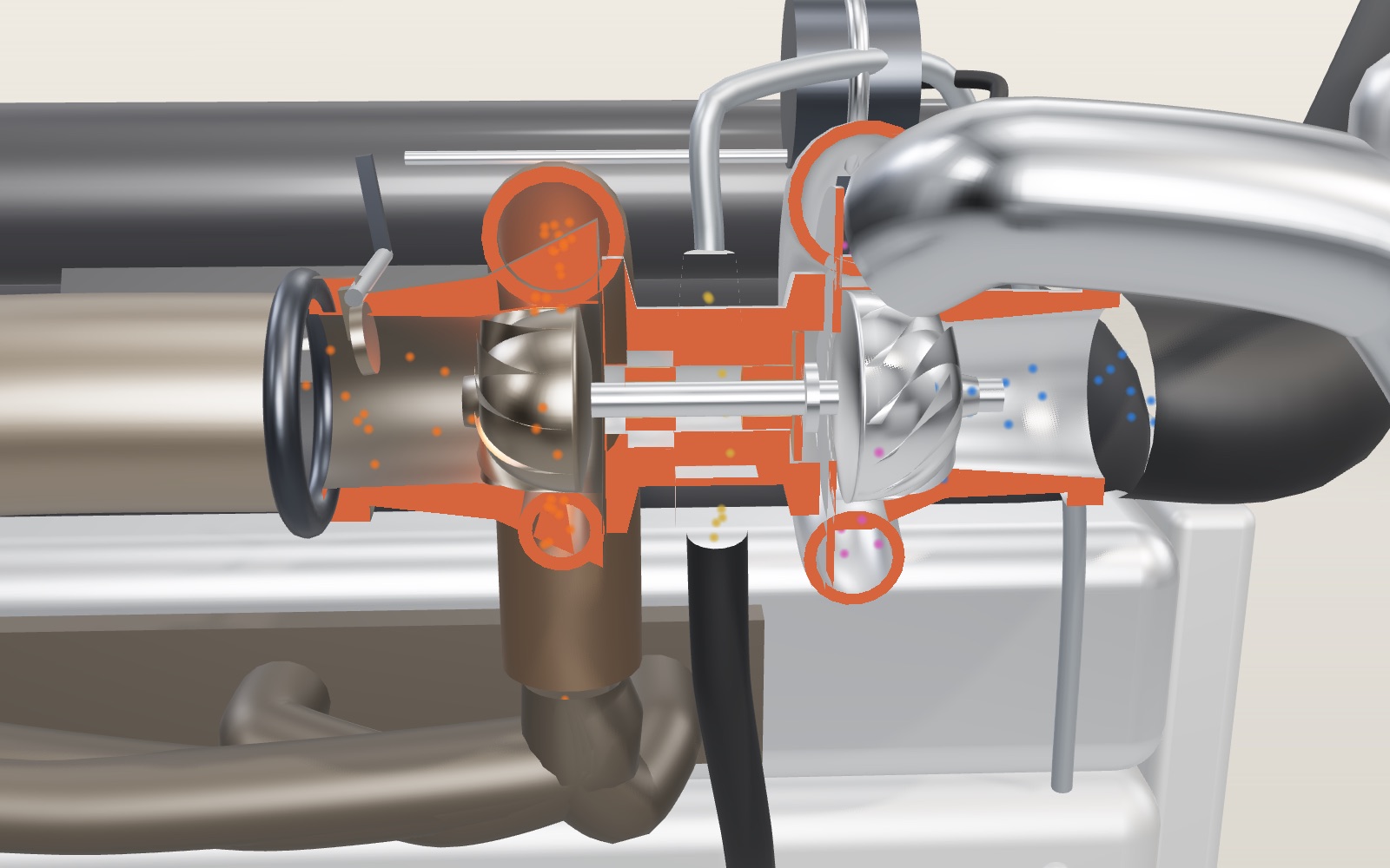
1 / 8 A turbo on a four-cylinder engine The turbo between the engine and the intercooler is cut along its shaft, and the red faces are where it was cut. Orange dots are exhaust; blue dots are fresh air and turn purple as they heat. The readout is worked out from the settings in Controls.
Drag to turn. Scroll or pinch to zoom.
Guide Parts Controls
01 A turbo on a four-cylinder engine The turbo between the engine and the intercooler is cut along its shaft, and the red faces are where it was cut. Orange dots are exhaust; blue dots are fresh air and turn purple as they heat. The readout is worked out from the settings in Controls.
02 Exhaust spins the turbine Gas from all four cylinders runs into the narrowing scroll, speeds up and swirls into the turbine wheel. At 4,000 rpm and full throttle the shaft in this model turns at about 142,000 rpm. The wheels on screen turn 2,000 times slower.
03 The compressor on the same shaft The compressor wheel sits on the other end of the same shaft, so it turns at exactly the same speed. It takes air in at the centre and flings it outwards, and the scroll around it turns that speed into pressure.
04 Oil keeps the shaft afloat The shaft spins inside two bronze bushes on a thin film of engine oil. The oil arrives through the braided line on top and drains out of the bottom, carrying heat away from the hot side too.
05 Squeezing air heats it With the intercooler switched off, air at one bar of boost leaves the compressor at about 115 °C. Hot air is thin: this charge is only 1.53 times as dense as the outside air, and the engine makes 95 kW.
06 The intercooler takes the heat out With the intercooler back on, the same air reaches the engine at 47 °C. At the same pressure it is now 1.85 times as dense as outside air, so each cylinder gets more oxygen and the output rises to 115 kW.
07 The wastegate caps the boost At 6,000 rpm the exhaust could drive the compressor well past the limit. The actuator opens the flap and about half of the gas skips the turbine, which holds the boost at one bar.
08 Turbo lag The engine is at 2,000 rpm on light throttle, then the throttle is floored. Watch the chart: the shaft needs about two seconds to wind up, and the boost follows it. Move the throttle slider to try it again.
Engine A 2.0-litre four-cylinder four-stroke petrol engine. Each cylinder draws in one charge of air every two crank turns. Exhaust manifold and downpipe Cast-iron runners gather the exhaust from all four cylinders and feed it to the turbine. The downpipe carries it away afterwards. Turbine housing A cast-iron scroll that narrows as it wraps around the wheel, so the gas speeds up and swirls inwards. Turbine wheel Eleven blades in heat-resistant alloy. Gas flows in at the rim and out along the axis, and its push turns the shaft. Shaft and bearings One steel shaft joins the two wheels. It runs in two floating bronze bushes, and a thrust bearing holds it against end load. Centre housing and oil The cool middle body. Engine oil arrives through the braided line on top, coats the bearings and drains out of the bottom. Compressor wheel Six full blades and six splitters in aluminium. Air comes in along the axis and is flung outwards at the rim. Compressor housing The aluminium scroll widens around the wheel and turns fast air into pressure before it leaves through the outlet. Wastegate A flap that opens a path around the turbine. The actuator pushes it open when boost reaches the limit. Intercooler A tube-and-fin core in the air stream at the front. In the model it removes 75 percent of the heat added by compression. Air filter, pipes and throttle Air enters through the filter, and after the intercooler it passes the throttle butterfly into the plenum and runners.