Loading the model
This device cannot show the 3D model. You can read the guide steps below as text.
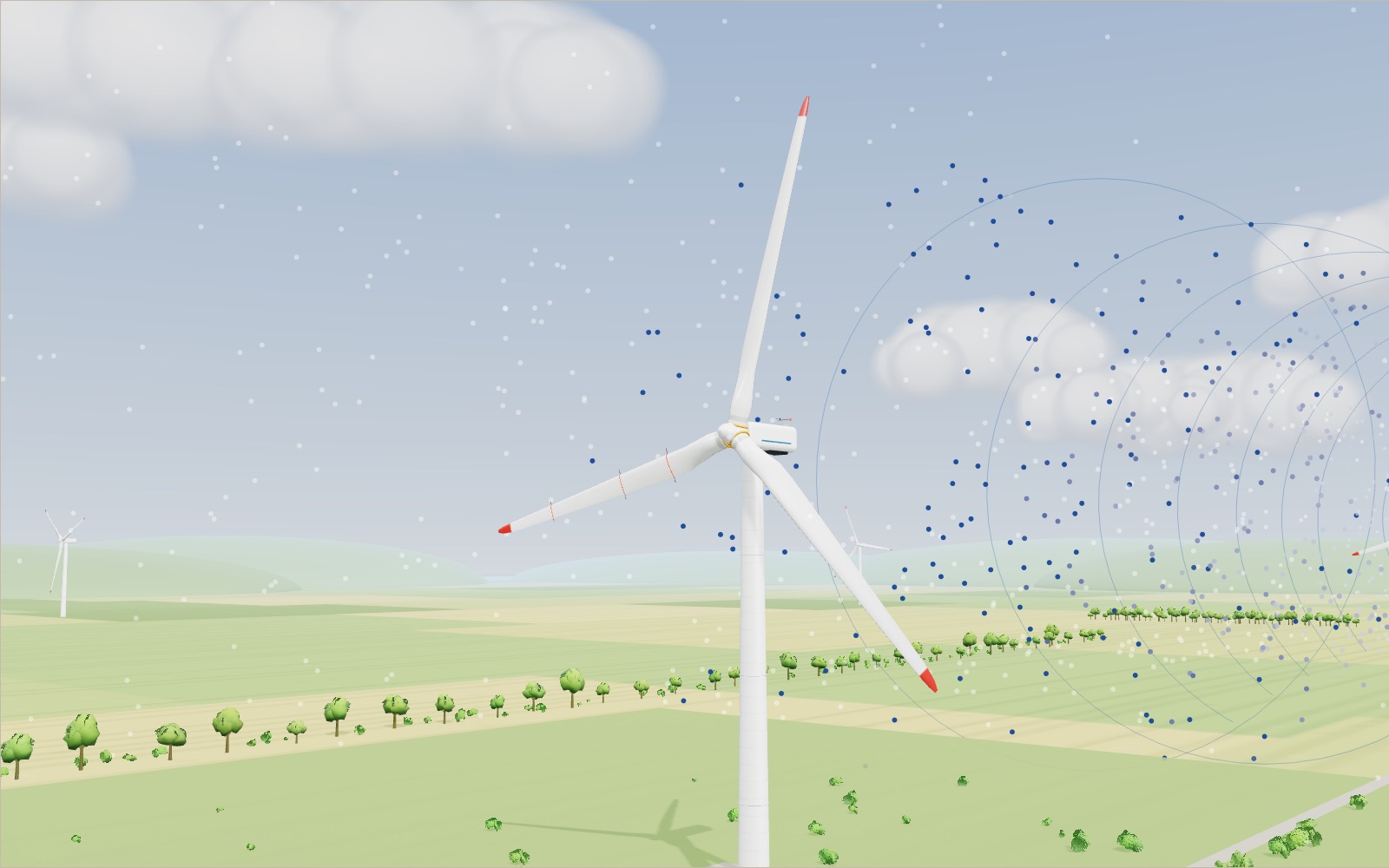
1 / 8 A 5 MW turbine in a field This is the NREL 5 MW reference turbine, a public design used for research. The rotor is 126 m across and the hub is 90 m above the ground. In an 8 m/s wind it turns at 9.2 rpm and gives 1.78 MW. The second turbine stands 630 m downwind, five rotor diameters away.
Drag to turn. Scroll or pinch to zoom.
Guide Parts Controls
01 A 5 MW turbine in a field This is the NREL 5 MW reference turbine, a public design used for research. The rotor is 126 m across and the hub is 90 m above the ground. In an 8 m/s wind it turns at 9.2 rpm and gives 1.78 MW. The second turbine stands 630 m downwind, five rotor diameters away.
02 Blade shape and twist Below 3 m/s the turbine waits: the blades are turned edge-on to the wind and the rotor is parked. The orange cuts show how the blade changes. Near the hub it is a round tube; further out it becomes a thick and then a thin airfoil, and the chord line twists by 13.3° from root to tip.
03 Why the tip moves so fast At 8 m/s the rotor turns 9.2 times a minute, yet the blade tips travel at 60 m/s. Tip speed divided by wind speed is the tip-speed ratio, here 7.55. At that ratio this rotor catches the largest share of the wind, 48.2 %.
04 Inside the nacelle The main shaft turns as slowly as the rotor. A three-stage gearbox raises the speed 97 times, so 9.2 rpm becomes about 890 rpm at the generator. The orange mark on the brake disc shows the fast shaft; the screen slows it down so you can follow it.
05 The power in the wind Power in the wind grows with the cube of its speed: P = ½ ρ A v³. At 11.4 m/s about 11.3 MW of wind passes through the rotor disc. The rotor takes 46.8 % of it and the generator gives 5 MW. No rotor can take more than 16/27, or 59.3 %: the Betz limit, drawn in blue on the chart.
06 Pitch keeps the power at 5 MW At 18 m/s the wind carries 44.5 MW through the rotor. The controller turns all three blades 14.9° toward the wind, so they meet it at a smaller angle and take less. Power stays at 5 MW. Switch off automatic pitch and hold it at 0°: the rotor would try to make 9.8 MW and overload the generator. Above 25 m/s the blades turn to 90° and the rotor stops.
07 The nacelle turns to face the wind The wind has swung 30°. The vane on the roof turns at once, but the yaw drives move the 240-tonne nacelle at only 0.3° a second, so the real turn takes 100 s. The screen runs it 20 times faster. With a 30° error the rotor makes 65 % of its power at 8 m/s.
08 The slow air behind Every watt the rotor takes comes out of the air, so behind it the wind is slower. At 630 m it is still 7.3 m/s instead of 8, and the second turbine makes 1.34 MW, 76 % of the first. Turn the wind by 20° and the wake misses it.
Blades Three glass-fibre blades, 61.5 m long. The chord is 4.65 m at its widest, 15.85 m from the centre, and 1.42 m near the tip. The red band at the tip is for aircraft. Blade sections (airfoils) The orange rings are cuts at 15.85 m, 28.15 m and 47.25 m. The root is a round tube, the middle uses thick DU airfoils and the outer third a thin NACA 64 shape. The black lines are chords: the one at 47.25 m sits 8.9° flatter than the one at 15.85 m. Hub and spinner A cast-iron hub 3 m across holds the three blade roots. The white nose cone in front of it, the spinner, keeps the rain out. Pitch bearings and drives Each blade sits on a large ring bearing (yellow) and is turned by its own motor. The orange tooth on the inner ring shows how far the blade has turned. The model limits them to 8° a second. Nacelle The housing on top of the tower, about 14 m long. With the drivetrain it weighs about 240 tonnes. A cooler sits on the roof. Main shaft A thick steel shaft carries the rotor's turning force into the nacelle. It turns at rotor speed, at most 12.1 rpm, and at rated power carries about 4.2 million newton metres. The orange key turns with it. Main bearing and bedplate The main bearing holds the shaft just behind the hub and takes the weight of the 110-tonne rotor. The bedplate underneath carries the whole drivetrain and sits on the yaw bearing. Gearbox and brake Three gear stages raise the speed 97 times, from 12.1 rpm to 1,173.7 rpm. The torque arms on each side pass the reaction into the bedplate. Brake and high-speed shaft The fast shaft leaves the gearbox at up to 1,173.7 rpm. The disc on it and the red calliper make the parking brake, used to hold the rotor still for maintenance. Generator Turns the fast shaft's work into electricity. In the model it converts 94.4 % of the shaft power; at rated speed it gives 5 MW. Cooler A radiator on the roof gets rid of the heat from the gearbox oil and the generator. At 5 MW, the 5.6 % lost in the generator alone is about 300 kW of heat. Yaw bearing and drives A ring bearing at the top of the tower and four yaw drives turn the whole nacelle to face the wind, at 0.3° a second on the real machine. Wind vane and anemometer On a mast at the back of the roof. The cups spin faster as the wind rises, and the vane points along the wind. When the vane and the nacelle disagree, the yaw drives start turning. Tower A steel tube 87.6 m tall, 6 m across at the base and 3.87 m at the top, in sections bolted together at flanges. It weighs about 347 tonnes. Foundation In the model, an eight-sided slab of reinforced concrete 20 m across, buried 3.6 m deep. Rings of anchor bolts tie the tower flange to it. The soil around it is cut away. Offshore turbines stand on a steel monopile instead, with a yellow transition piece and a work platform above the waves (pick an offshore turbine in the list below the stage). Wake The dots move with the air, four times faster than real. Behind the rotor the air is slower (blue) and spins a little against the rotor. The pale cone shows how the wake spreads. Second turbine The same 5 MW machine standing 630 m downwind, five rotor diameters away. Its tag shows the wind it receives and the power it makes, both lower when it sits in the first turbine's wake.