FIG. 78How It Works
How a wind turbine works: why the blades twist in strong wind
A turbine with 61-metre blades makes no more power in a gale than in a stiff breeze, because above 11.4 metres a second it turns its blades out of the wind.
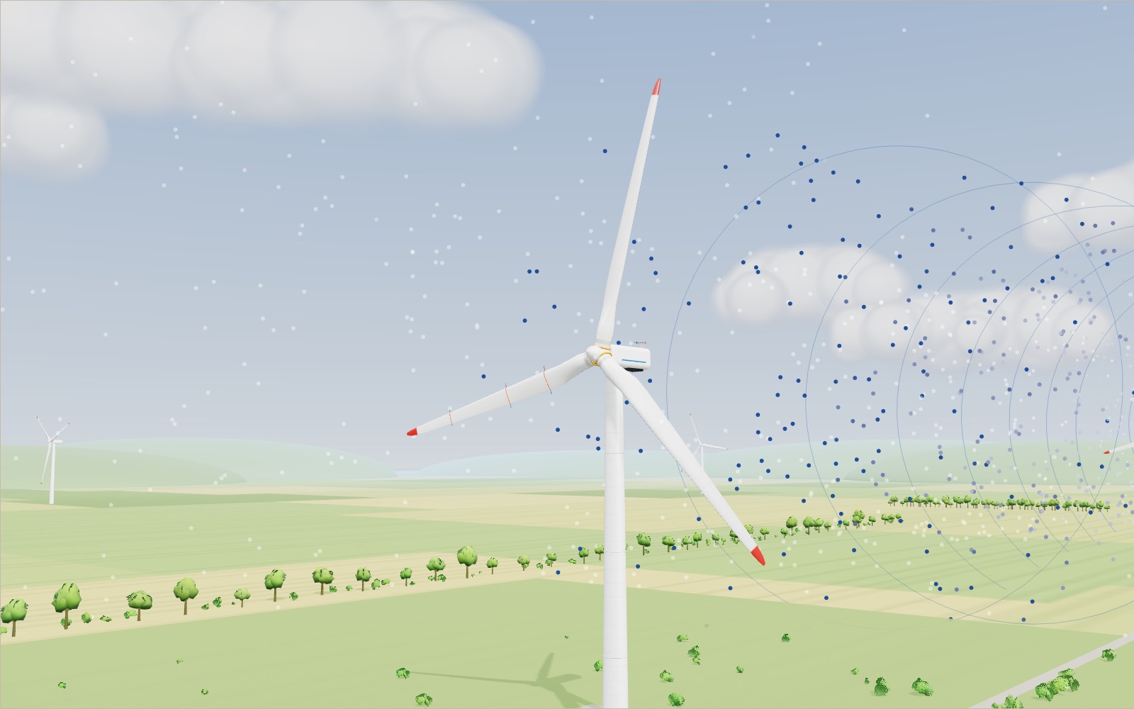
This device cannot show the 3D model. You can read the guide steps below as text.
1 / 8 A 5 MW turbine in a fieldThis is the NREL 5 MW reference turbine, a public design used for research. The rotor is 126 m across and the hub is 90 m above the ground. In an 8 m/s wind it turns at 9.2 rpm and gives 1.78 MW. The second turbine stands 630 m downwind, five rotor diameters away.
Drag to turn. Scroll or pinch to zoom.
What the model shows
A wind turbine turns its blades around their long axes to control how much force the wind applies to the rotor. In strong wind, this pitch adjustment limits power and loads instead of taking all the available energy. Above the cut-out speed, the turbine feathers its blades and stops.
From a motorway, a wind turbine looks as if it is barely moving. The blades swing round about once every five seconds, slowly enough to count. Yet the tips of those blades are travelling at close to 300 km/h, and the machine at the top of the tower can supply a few thousand homes. This exhibit takes one large turbine apart to show how a slow, heavy rotor turns moving air into electricity, and why it deliberately throws power away when the wind gets strong.
The model is the NREL 5 MW reference turbine. Researchers at the US National Renewable Energy Laboratory (now the National Laboratory of the Rockies, NLR) defined it in 2009 so that anyone could run simulations on the same machine. It is based closely on a real turbine, the REpower 5M. The rotor is 126 m across, the hub sits 90 m above the ground and the three blades are each 61.5 m long. Every size in the model is drawn in metres, so the service van at the foot of the tower is to scale.
Use the wind speed slider to move along the power curve. The rotor speeds up, the blades turn on their bearings and the red dot on the chart follows. The wind direction slider makes the nacelle swing round, and the dots in the air show how the wind slows down behind the rotor before it reaches the second turbine 630 m away.
Where the power in the wind comes from
Moving air has kinetic energy. Each second, a column of air as wide as the rotor and as long as the wind speed passes through the rotor disc. Its mass grows with the wind speed and its energy per kilogram grows with the square of the speed, so the power carried by the wind grows with the cube:
P = ½ ρ A v³
Here ρ is the density of the air (1.225 kg/m³ at sea level), A is the area swept by the blades and v is the wind speed. For this rotor A = π × 63² = 12,469 m². At 8 m/s, that gives 3.91 MW passing through the disc. At 11.4 m/s it is 11.3 MW, and at 25 m/s it is 119 MW.
The cube is the reason wind sites matter so much. A wind of 6 m/s and one of 12 m/s sound similar, but the second carries eight times as much power. Per square metre of rotor, an 8 m/s breeze carries 314 W and a 12 m/s wind 1,058 W.
A turbine only takes part of this. The share it takes is the power coefficient, Cp, and the full equation for the shaft power is P = ½ ρ A v³ Cp. The readout in the corner of the stage writes it out with the current numbers, and multiplies by the generator efficiency of 94.4 %.
Why no rotor can catch more than 59.3 %
A rotor cannot stop the wind dead. If it did, the air would pile up in front of it and no more would flow through. If it lets the air through untouched, it takes nothing. The best result lies in between, and in 1919 the German engineer Albert Betz worked out where.
Treat the rotor as a thin disc that slows the air. Call the fraction by which the air slows at the disc a, the axial induction factor. Conservation of mass and momentum gives Cp = 4a(1 − a)². The largest value comes at a = 1/3, when the air at the disc has slowed to two thirds of the wind speed and the air far behind to one third. The maximum is
Cp = 16/27 ≈ 0.593
Finding the peak numerically gives the same value: 0.59259 at a = 0.3333. This is the Betz limit, drawn as the blue dotted line on the power chart. The NREL rotor reaches a power coefficient of 0.482 at its best setting, 81 % of the limit. The rest is lost to drag on the blades, the swirl left in the wake and the air that escapes round the tips.
The blade is a wing that moves sideways
Each blade works like an aircraft wing. The difference is that it travels in a circle across the wind, so the air it meets comes from two directions at once. The wind blows through the rotor plane, and the blade's own motion makes a headwind along the plane. The sum of the two is the relative wind, and that is the air the blade actually feels.
The small panel at the bottom right of the stage draws this for a slice of blade 47 m from the centre, three quarters of the way out. At 8 m/s that slice moves at 45 m/s, while the wind through the disc (already slowed by the rotor) is about 6.6 m/s. The relative wind therefore arrives only 8.3° away from the rotor plane. The airfoil is set so that it meets this air at a small angle of attack, about 6°, where it gives plenty of lift for little drag. The lift is roughly at right angles to the relative wind, so it leans forward in the direction of travel and pulls the blade round.
Closer to the hub, the blade moves more slowly but the wind is the same, so the relative wind arrives at a steeper angle. That is why the blade is twisted. In the NREL table the chord line is set at 13.3° near the root and falls to 0.1° at the tip. The orange cuts on blade 1 show three slices: the one at 47.25 m sits 8.9° flatter than the one at 15.85 m.
The shape of the slices changes too. The root is a round tube, because it must carry the bending of a 61.5 m beam into the hub. Moving out, it becomes a thick DU airfoil (40 % to 21 % as thick as it is wide), and the outer third uses a thinner NACA 64 shape. The widest chord, 4.65 m, is near the root, and the chord shrinks to 1.42 m near the tip.
Tip speed and the tip-speed ratio
The tip-speed ratio, λ, is the speed of the blade tip divided by the wind speed. It is the number that decides how well a rotor works. If the rotor turns too slowly for the wind, the blades meet the air at too steep an angle and stall. If it turns too fast, the angle becomes too small, or negative, and the blades act as a brake.
For the NREL rotor the best ratio is 7.55. At 8 m/s, the tips then move at 60 m/s and the rotor turns at 9.2 rpm. The controller does not measure the wind for this; it sets the generator torque from the generator speed so that the rotor settles near the best ratio by itself. Watch the readout between 7 and 10 m/s: the wind changes, the rotor speed changes with it and λ stays at 7.55.
The tips cannot go on speeding up for ever. Noise grows quickly with tip speed, so the NREL design limits the rotor to 12.1 rpm, a tip speed of 80 m/s (287 km/h). In the model the rotor reaches that limit at 10.6 m/s. Between there and rated wind, the ratio falls and Cp slips from 0.482 to about 0.47.
At low wind the rotor also has a floor. The real machine never turns slower than 6.9 rpm while it is producing. In the model, that floor holds from 3 to 6 m/s, so the ratio is higher than ideal and the rotor makes 33 kW at 3 m/s and 181 kW at 4 m/s.
From 12 rpm to 1,174 rpm
A slow rotor makes a large turning force, or torque. At rated power the main shaft carries about 4.2 million newton metres while turning at 12.1 rpm. A generator that could use that directly would have to be very large. The NREL design, like the REpower machine, uses a gearbox instead.
The main shaft runs from the hub into the nacelle on a main bearing. Three gear stages raise the speed 97 times, so 12.1 rpm becomes 1,173.7 rpm on the high-speed shaft. That shaft carries the parking brake disc and drives the generator, which turns 94.4 % of the shaft power into electricity. Switch on "See inside" to look through the nacelle shell. The orange key on the main shaft turns with the rotor; the mark on the brake disc spins much faster, though the screen holds it to a speed you can follow.
Some turbines skip the gearbox and use a large, slow generator with many poles, called direct drive. The US Department of Energy describes both layouts. The gearbox lets the generator be smaller; direct drive does without the gearbox altogether.
The power curve has four parts
The black line on the chart is the power curve of the model, and it has a shape that every large turbine shares.
Below the cut-in speed of 3 m/s there is too little energy to be worth collecting. The rotor is parked and the blades are turned edge-on to the wind.
From 3 m/s to rated speed, output climbs steeply because of the cube. The rotor follows the best tip-speed ratio where it can, and the dot stays a fixed fraction below the blue Betz line.
At the rated wind speed of 11.4 m/s the generator reaches 5 MW. Beyond that the curve is flat: more wind does not mean more power.
At the cut-out speed of 25 m/s the turbine shuts down to protect itself. The blades turn to 90° and the rotor stops. The power drops straight to zero, which is why the chart has a cliff on its right-hand side.
How pitch holds the power at 5 MW
At 18 m/s the wind carries 44.5 MW through the rotor, nine times the rating. If the blades stayed where they were, the rotor would try to deliver about 9.8 MW. You can see this by switching off automatic pitch and setting the pitch to 0°: a dashed orange curve appears on the chart, the dot climbs above 5 MW and the readout warns of overload.
The cure is to turn each blade about its own long axis, toward the wind. This is called pitching to feather. As the blade turns, its leading edge points more into the relative wind, the angle of attack drops and the blade gives less lift. The section panel shows the change: at 18 m/s the slice at 47 m meets the air at an angle of attack close to zero.
The NREL report lists the pitch needed to hold rated power at each wind speed. It is 3.8° at 12 m/s, 10.5° at 15 m/s, 14.9° at 18 m/s and 23.5° at 25 m/s. The model's power coefficient formula is fitted to those values, so the pitch you read at 18 m/s is the NREL figure. The power coefficient there is only 0.119: the rotor now takes about an eighth of the wind's power, by choice.
Pitch motors cannot move a 17-tonne blade instantly. The NREL controller is limited to 8° a second, and so is the model. Jump the wind from 8 to 18 m/s and you can watch the pitch climb over about two seconds while the rotor holds its speed.
Turning to face the wind
The rotor only works well if it faces the wind squarely. A wind vane and a cup anemometer on the roof of the nacelle measure the direction and speed, and the yaw drives turn the whole nacelle on a large ring bearing at the top of the tower. The DOE describes this arrangement for upwind turbines, which have their rotor on the windward side of the tower, like this one.
The nacelle and rotor together weigh about 350 tonnes, so the NREL design turns them at only 0.3° a second. A 30° change in the wind takes 100 seconds to follow. The model draws it 20 times faster. Move the wind direction slider and the vane on the roof swings round at once, while the nacelle follows more slowly and the yaw error in the readout counts down.
While the error lasts, the rotor sees only the part of the wind that blows along its axis. In the simple picture the model uses, power falls with the cube of the cosine of the error. At 30°, that leaves 65 % of the power.
The slower air behind a turbine
Energy taken from the air leaves the air slower. Behind the rotor there is a wake: a widening tube of slower, swirling air that recovers gradually as faster air mixes in from the sides. The flow dots show it in blue, and the pale rings show how far it has spread.
The model uses the wake model that N. O. Jensen of Risø National Laboratory published in 1983. The wind just behind the rotor is slowed by a fraction 1 − √(1 − Ct), where Ct is the thrust coefficient, and the wake widens in a straight line at a rate of 0.1 m for every metre downstream, the value Jensen used. The slowdown then spreads over the growing area:
v_wake = v (1 − (1 − √(1 − Ct)) / (1 + 0.1 x / R)²)
At 8 m/s the model rotor has Ct = 0.59. At 630 m, five diameters downstream, the wake has grown to a radius of 126 m and the wind is 7.3 m/s. That is only 9 % slower, but because of the cube the second turbine makes 1.34 MW against 1.78 MW for the first, 76 %. Turn the wind by 20° and the wake slides past the second rotor.
Above about 12 m/s the wake matters much less. The first turbine is pitching and taking a small share of the wind, so it leaves less of a hole, and the second turbine is past rated wind anyway.
Tower and foundation
The tower is a steel tube 87.6 m tall, 6 m across at the base and 3.87 m at the top, built from sections bolted together at flanges. It weighs about 347 tonnes. It has to carry the weight of the nacelle and rotor and, more importantly, the thrust of the wind on the rotor, which tries to bend it over like a lever 90 m long.
All that ends in the foundation. The model shows a common type for land sites: a wide slab of reinforced concrete buried a few metres down, with a pedestal and rings of anchor bolts that grip the bottom flange of the tower. Its size here is a model value, 20 m across and 3.6 m deep. The soil around it is cut away so that you can see it; on a real site it is covered and grassed over.
How this turbine compares with others
The NREL turbine is a 2009 design. Research labs have since published larger reference turbines, and the DOE tracks the size of the machines actually built in the United States. The table puts them side by side. The last row is worked out from the DOE's growth figures (hub height up 83 %, swept area up about 670 % and rating up 375 % since 1998 to 1999), so it is approximate.
| Turbine | Rating | Rotor diameter | Hub height | Notes |
|---|---|---|---|---|
| NREL 5 MW reference (2009), this model | 5 MW | 126 m | 90 m | Rotor up to 12.1 rpm, tips at 80 m/s, geared |
| IEA Wind 3.4 MW land-based reference (2019) | 3.4 MW | 130 m | 110 m | Designed for land sites |
| IEA Wind 10 MW offshore reference (2019) | 10 MW | 198 m | 119 m | Direct drive, no gearbox |
| GE Haliade-X, as cited by NREL (2020) | 12 MW | 218 m | not given | A commercial offshore machine |
| IEA Wind 15 MW offshore reference (2020) | 15 MW | 240 m | 150 m | Rotor 5 to 7.56 rpm, tips at 95 m/s, 65 t blades, Cp 0.489, rated at 10.59 m/s |
| Average new US land turbine, 2023 | 3.4 MW | 133.8 m | 103.4 m | DOE figures |
| Average new US land turbine, 1998 to 1999 | about 0.7 MW | about 48 m | about 57 m | Worked out from the DOE growth figures |
The list below the stage goes further, with 22 machines from the two-bladed Smith-Putnam of 1941 to the 22 MW IEA design, including Korea's offshore farms at Tamra, Hallim and the Southwest demonstration site. Pick one and the stage turbine is redrawn at that rotor size, hub height and rating, next to a person, a city bus and the 63 Building in Seoul for scale. Offshore turbines stand in the sea on a monopile.
Two things stand out. The model's rotor is close to today's average land turbine, but its rating is higher, because it was defined for offshore studies where a bigger generator pays. And the bigger the rotor, the slower it turns: the 240 m IEA rotor tops out at 7.56 rpm, yet its tips move faster than the NREL rotor's, at 95 m/s. The NREL 5 MW report gives noise as the reason for its own tip-speed limit.
Specific power and capacity factor
The rating of a turbine says what it makes at best. How much it makes over a year depends on how often the wind lets it reach that. Engineers use two numbers for this. Specific power is the rating divided by the swept area. Capacity factor is the energy actually produced in a period divided by what the turbine would make if it ran at its rating all the time.
Work out the specific power from the exhibit's numbers. The NREL 5 MW rotor sweeps 12,469 m², so its specific power is 5,000,000 W / 12,469 m² = 401 W/m². The IEA 15 MW reference rotor has a 240 m diameter, so A = π × 120² = 45,239 m² and the specific power is 15,000,000 / 45,239 = 332 W/m². The larger rotor has a bigger generator behind it in proportion, but a smaller one per square metre of rotor.
A low specific power means a large rotor for its generator. The rotor then collects enough wind to fill the generator in lighter winds, so it spends more hours near its rating. NREL's report on the IEA Wind reference turbines says survey respondents asked for a land-based reference with a specific power under 250 W/m², because low-wind-speed turbines reach much higher capacity factors. It also quotes GE's estimate for the Haliade-X offshore turbine: a specific power of 315 W/m² and a capacity factor of 63 % on a tower about 150 m tall. That 63 % is the manufacturer's estimate for one design, not a measured national average, and this page does not state measured averages because no checked source here gives them.
Tip speed, rotor speed and noise
The speed of a blade tip is the rotor speed in radians per second times the radius. For the NREL rotor at its limit, 12.1 rpm is 12.1 × 2π / 60 = 1.267 rad/s, and 1.267 × 63 m = 79.8 m/s, which the NREL table rounds to 80 m/s. For the IEA 15 MW rotor, 7.56 rpm gives 0.792 rad/s and 0.792 × 120 m = 95 m/s.
Because the tip speed is capped, a larger rotor must turn more slowly. Doubling the radius at the same tip speed halves the rpm. This is why the 240 m rotor turns at 7.56 rpm and the 126 m rotor at 12.1 rpm, although the larger one has the faster tips.
The cap exists mainly because of noise. The NREL report says the transition region it adds to the controller, called Region 2½, is there to limit tip speed, and with it noise, at rated power. The IEA Wind survey of designers found that most recommended a maximum tip speed of 80 to 90 m/s for a land-based reference, and 90 to 110 m/s for an offshore one. These are design choices, not laws of nature.
What holds an offshore turbine up
The exhibit draws a land foundation, but the NREL 5 MW report notes that offshore support structures depend on the site's water depth, soil, wind and waves. It names the main types: fixed-bottom monopiles, gravity bases, space-frames such as tripods, quadpods and lattice jackets, and floating structures.
The IEA 15 MW reference turbine uses a monopile, a single steel tube driven into the sea bed. It is designed for a water depth of 30 m. The pile has an outer diameter of 10 m, goes 45 m into the bed and weighs 1,318 t; the tower above it weighs 860 t. The hub is 150 m up, which leaves 30 m of clearance between the water surface and the lowest point of a blade of up to 120 m. The report says a 10 m pile pushes the limits of manufacturing and installation. For deeper water, the same turbine has a floating version on a semisubmersible platform designed at the University of Maine, described in a separate report. The US Department of Energy has also funded research on floating wind design and manufacturing.
Design also has to avoid resonance. The report puts the first natural frequency of the tower and pile at 0.17 Hz, between the rotor rotation frequency (1P) and the blade passing frequency (3P) at all wind speeds. It adds that this is also clear of the highest-energy ocean waves at a generic East Coast site, 0.10 to 0.13 Hz.
Common misunderstandings
More wind does not mean more power without limit. Past 11.4 m/s the model turbine holds 5 MW, and past 25 m/s it makes none. The wind still carries more power; the turbine chooses not to take it.
The Betz limit is not a flaw in the blades. It holds for any rotor in open air. The 59.3 % applies to the power in the air that passes through the rotor disc. The NREL rotor takes 48.2 % at best.
The blade tip does not move at the wind speed. At the best setting it moves 7.55 times faster than the wind, and the blade is always flying in a relative wind that is mostly its own motion.
The rating is not the average output. A turbine rated at 5 MW seldom runs at 5 MW. Its average, divided by its rating, is the capacity factor, and the cube law explains why the figure is well below 100 %: most hours have winds below rated speed.
Try it on the screen
- Move the wind speed slider to 8 m/s. The readout shows a tip-speed ratio of 7.55 and about 9.2 rpm. Move it to 10 m/s and the ratio stays the same while the rpm rises.
- Keep going to 10.6 m/s. The rotor stops at 12.1 rpm and the ratio begins to fall.
- Go above 11.4 m/s. The power line flattens at 5 MW and the pitch angle starts to rise.
- Switch off automatic pitch and set 0° at 18 m/s. The dashed curve rises above 5 MW and the readout warns of overload.
- Switch on "See inside". The orange key on the main shaft turns slowly; the mark on the brake disc turns much faster, at a speed the screen holds to something you can follow.
- Use the wind direction slider and watch the yaw error count down. Then pick the IEA Wind 15 MW reference in the turbine list and compare its rotor and hub with the NREL machine next to the bus and the 63 Building.
What the model leaves out
The wind in the model is steady and the same at every height. Real wind gusts, turns and is stronger higher up, so a blade at the top of its circle feels more wind than at the bottom.
The power coefficient comes from a general formula used in many control textbooks, fitted to the NREL peak (0.482 at a tip-speed ratio of 7.55) and to the NREL pitch table. It is not a blade-element calculation, so the numbers between those points are model values. The angle of attack in the section panel uses the induction factor of the whole rotor and ignores the swirl near the blade, so it is a guide rather than a measurement.
The NREL controller has a smooth start-up region and a speed region with generator slip; the model replaces them with simple limits. It does not model tower shadow, blade bending, ice, the grid or the converter that matches the generator to the grid. Yaw is 20 times faster on screen than in reality and the flow dots move 4 times faster than the air.
A worked example: a 150 m rotor in a 10 m/s wind
The exhibit's formula works for any size, so try a rotor that is not in the model. Assume a rotor diameter of 150 m, a wind of 10 m/s, sea-level air at 1.225 kg/m³, a power coefficient of 0.45 and a generator efficiency of 94.4 %. These are assumed values for the exercise, not the figures of a particular machine.
The swept area is A = π × 75² = 17,671 m². The wind carries ½ × 1.225 × 17,671 × 10³ = 10.8 MW through the disc, which is 612 W for every square metre. The Betz limit allows at most 16/27 of that, 6.41 MW. A power coefficient of 0.45 gives 4.87 MW at the shaft, and the generator turns that into 4.60 MW of electricity.
Two lessons follow. Doubling the diameter would quadruple the area, but doubling the wind speed would multiply the power by eight. And even a good rotor delivers well under half of the power that the wind carries through it.
Questions
How does a wind turbine make electricity?
The wind flows over the blades, which are shaped like wings. The lift on them turns the rotor, and the rotor turns a shaft. In a geared turbine like this one, a gearbox raises the shaft speed 97 times and drives a generator, which turns the motion into electricity.
What wind speed does a wind turbine need?
The NREL 5 MW turbine starts producing at 3 m/s, reaches its full 5 MW at 11.4 m/s and shuts down above 25 m/s. Because power grows with the cube of wind speed, most of the energy comes from the middle of that range.
Why do wind turbines stop in very strong wind?
Above the cut-out speed the loads on the blades and tower become too large. The turbine turns its blades to 90°, edge-on to the wind, and brakes the rotor. In this model that happens above 25 m/s.
What is the Betz limit?
It is the most power any rotor in open air can take from the wind: 16/27, about 59.3 %. Albert Betz derived it in 1919 by treating the rotor as a thin disc that slows the air. The best case slows the air at the rotor to two thirds of the wind speed.
Why are wind turbine blades twisted?
The inner part of a blade moves more slowly than the tip, so the air reaches it at a steeper angle. The twist keeps the angle of attack small along the whole length. On the NREL blade the chord line turns through 13.3° from root to tip.
How fast do the blade tips move?
At the rotor's top speed of 12.1 rpm, the tips of a 126 m rotor travel at 80 m/s, about 287 km/h. The NREL design caps the speed there mainly to limit noise.
Why does a turbine make the same power at 15 m/s as at 12 m/s?
Above the rated wind speed, the pitch system turns the blades toward the wind so they take a smaller share of it. The generator stays at 5 MW. Without pitch, the rotor would overload the generator and gearbox.
Why are wind turbines spaced far apart?
Each turbine leaves a wake of slower air behind it. In the model, the turbine 630 m downwind gets 7.3 m/s instead of 8 m/s and makes about a quarter less power. Spacing turbines further apart, or across the usual wind direction, reduces this loss.
What is the capacity factor of a wind turbine?
It is the energy a turbine actually produces over a period, divided by what it would produce running at its rating the whole time. A turbine with a large rotor for its generator, meaning a low specific power, reaches its rating in lighter winds and so has a higher capacity factor. GE's estimate for the Haliade-X, cited by NREL, is 63 %, but that is a design estimate and not a measured average.
Why do bigger wind turbines turn more slowly?
Blade tip speed is capped, mainly because of noise. At a fixed tip speed, a larger radius means fewer turns per minute. The 126 m NREL rotor turns at up to 12.1 rpm with tips at 80 m/s, and the 240 m IEA rotor at up to 7.56 rpm with tips at 95 m/s.
How is an offshore wind turbine fixed to the sea bed?
It depends on the site. The main types are monopiles, gravity bases, space-frames such as tripods and jackets, and floating platforms. The IEA 15 MW reference turbine stands on a monopile 10 m wide that goes 45 m into the bed, designed for a water depth of 30 m.
Terms
- Rotor: the blades and the hub, the part that turns.
- Nacelle: the housing on top of the tower that holds the drivetrain.
- Airfoil: the cross-section shape of a blade or wing.
- Chord: the straight line from the leading edge to the trailing edge of an airfoil, and its length.
- Twist: the change in the chord's angle along the blade.
- Angle of attack: the angle between the chord and the air arriving at the blade.
- Relative wind: the wind as the moving blade feels it, the sum of the real wind and the blade's own motion.
- Power coefficient (Cp): the share of the wind's power that the rotor turns into shaft power.
- Axial induction factor (a): the fraction by which the rotor slows the wind at the disc.
- Thrust coefficient (Ct): the push of the wind on the rotor, compared with ½ ρ A v².
- Tip-speed ratio (λ): the speed of the blade tip divided by the wind speed.
- Betz limit: the highest possible power coefficient, 16/27.
- Cut-in, rated and cut-out wind speed: where the turbine starts, reaches full power and shuts down.
- Pitch: turning a blade about its long axis.
- Feather: pitching a blade to about 90° so it lies edge-on to the wind.
- Yaw: turning the nacelle about the tower axis.
- Wake: the slower, swirling air behind a rotor.
Sources
- J. Jonkman, S. Butterfield, W. Musial and G. Scott, Definition of a 5-MW Reference Wind Turbine for Offshore System Development, NREL/TP-500-38060 (2009): Table 1-1 (gross properties), Table 2-2 (blade mass), Table 3-1 (blade chord, twist and airfoils), Table 5-1 (drivetrain), Tables 6-1 and 6-2 (tower), Table 7-1 (pitch angles in Region 3), Table 7-2 (control properties). https://docs.nlr.gov/docs/fy09osti/38060.pdf (checked 17 October 2026)
- National Laboratory of the Rockies (NLR) research hub, record for the same report. https://research-hub.nlr.gov/en/publications/definition-of-a-5-mw-reference-wind-turbine-for-offshore-system-d (checked 17 October 2026)
- NLR, Wind Energy Research. https://www.nlr.gov/wind/ (checked 17 October 2026)
- US Department of Energy, How Do Wind Turbines Work? https://www.energy.gov/eere/wind/how-do-wind-turbines-work (checked 17 October 2026)
- US Department of Energy, How a Wind Turbine Works: Text Version (parts of a turbine: pitch system, yaw drive, wind vane, anemometer, gearbox). https://www.energy.gov/eere/wind/how-wind-turbine-works-text-version (checked 17 October 2026)
- US Department of Energy, Wind Turbines: the Bigger, the Better (average hub height, rotor diameter and rating of US land-based turbines in 2023). https://www.energy.gov/eere/articles/wind-turbines-bigger-better (checked 17 October 2026)
- E. Gaertner and others, Definition of the IEA Wind 15-Megawatt Offshore Reference Wind Turbine, NREL/TP-5000-75698 (2020), Table ES-1 and the introduction (GE Haliade-X). https://docs.nlr.gov/docs/fy20osti/75698.pdf (checked 17 October 2026)
- P. Bortolotti and others, IEA Wind TCP Task 37: Systems Engineering in Wind Energy, WP2.1 Reference Wind Turbines, NREL/TP-5000-73492 (2019) (3.4 MW land-based and 10 MW offshore turbines). https://docs.nlr.gov/docs/fy19osti/73492.pdf (checked 17 October 2026)
- US Energy Information Administration, Wind explained. https://www.eia.gov/energyexplained/wind/ (checked 17 October 2026)
- US Department of Energy, WINDExchange. https://windexchange.energy.gov/ (checked 17 October 2026)
- N. O. Jensen, A Note on Wind Generator Interaction, Risø-M-2411, Risø National Laboratory (1983). https://backend.orbit.dtu.dk/ws/portalfiles/portal/55857682/ris_m_2411.pdf (checked 17 October 2026)
- M. Ragheb and A. M. Ragheb, Wind Turbines Theory: The Betz Equation and Optimal Rotor Tip Speed Ratio, in Fundamental and Advanced Topics in Wind Power, InTech (2011). https://cdn.intechopen.com/pdfs/16242/InTechWind_turbines_theory_the_betz_equation_and_optimal_rotor_tip_speed_ratio.pdf (checked 17 October 2026)
- Turbine list below the stage: each row links its own source. The main ones:
- Doosan Enerbility, Wind Power Model Line-up. https://www.doosanenerbility.com/en/business/wind_energy_lineup (checked 17 October 2026)
- Doosan Enerbility, DS205-8MW news (205 m rotor, 100 m blades). https://www.doosanenerbility.com/en/about/news_board_view?id=21000587&page=10&pageSize=9 (checked 17 October 2026)
- Vestas, V236-15.0 MW. https://www.vestas.com/en/energy-solutions/offshore-wind-turbines/V236-15MW (checked 17 October 2026)
- Siemens Gamesa, SG 14-236 DD. https://www.siemensgamesa.com/global/en/home/products-and-services/offshore/wind-turbine-sg-14-236-dd.html (checked 17 October 2026)
- GE Vernova, Haliade-X. https://www.gevernova.com/wind-power/offshore-wind/haliade-x-offshore-turbine (checked 17 October 2026)
- London Array (hub 87 m above the sea). https://londonarray.com/ (checked 17 October 2026)
- Vattenfall, Horns Rev 1. https://powerplants.vattenfall.com/horns-rev/ (checked 17 October 2026)
- NASA, The Mod-2 Wind Turbine Development Project (1981). https://ntrs.nasa.gov/api/citations/19810019068/downloads/19810019068.pdf (checked 17 October 2026)
- F. Zahle and others, IEA Wind 22 MW reference turbine webinar slides, NREL (2024). https://docs.nlr.gov/docs/fy24osti/89807.pdf (checked 17 October 2026)
- US Department of Energy, Offshore Wind Research and Development (funded research on floating offshore wind). https://www.energy.gov/eere/wind/offshore-wind-research-and-development (checked 23 October 2026)
- Model values (the power coefficient fit, the power curve, pitch, yaw and wake figures, the Betz maximum) were worked through by hand.
More exhibits
Electric motor simulator: how it works, step by step
Eight motors, from Faraday's wire in mercury in 1821 to the magnets inside an electric car, all turning on the same push between current and field.
How lightning and thunder work
A lightning channel heats the air to about five times the temperature of the Sun’s surface, and its thunder needs about 3 seconds to cover each kilometre to you.
How electricity gets to your home
Electricity leaves the power station at 345,000 volts and reaches the outlet at 220, because high voltage keeps the current, and the heat lost in the wires, small.
How a lithium-ion battery works: where the ions go on charge
Each time an 18650 cell charges, about 7 × 10²² lithium ions leave a metal oxide and squeeze in between sheets of graphite.
How a microwave oven works: the magnetron that makes the waves
The waves inside a microwave oven are 12.2 cm long, so without a turntable the hot spots in your food sit about 6 cm apart.
How a touchscreen works: how the glass finds your finger
Under the glass of a phone lies a grid of transparent electrodes, and your finger shows up as a small dip in the charge passing between them.
How does a vending machine recognise coins?
A 100 won coin is not attracted to a magnet, yet the magnet inside a vending machine is what tells it from a copper fake.
How a phonograph works: from tinfoil to cassette and CD
Edison's first phonograph cut a voice into tinfoil in 1877, and the same needle played it back from a groove 2.54 mm apart.
How to tie knots: 40 knots step by step
In one set of break tests a bowline kept about 63% of the rope's strength and a sheet bend about half.
How a solar panel works
In full sun a 60-cell rooftop panel makes about 300 watts, and all of it comes from an electric field sitting inside each slice of silicon.

How a QR code is read
Cover 30 % of a QR code with your hand and a phone still reads it. Cover one corner and it does not.
How a 3D printer works, layer by layer
A 20 mm cube printed in 0.2 mm layers is exactly 100 layers, each drawn by a nozzle 0.4 mm wide.