FIG. 68How It Works
How fibre optics and submarine cables work
Light in a submarine cable stays inside a glass core 8.2 micrometres wide for thousands of kilometres because it meets the core wall at more than 84.5°.
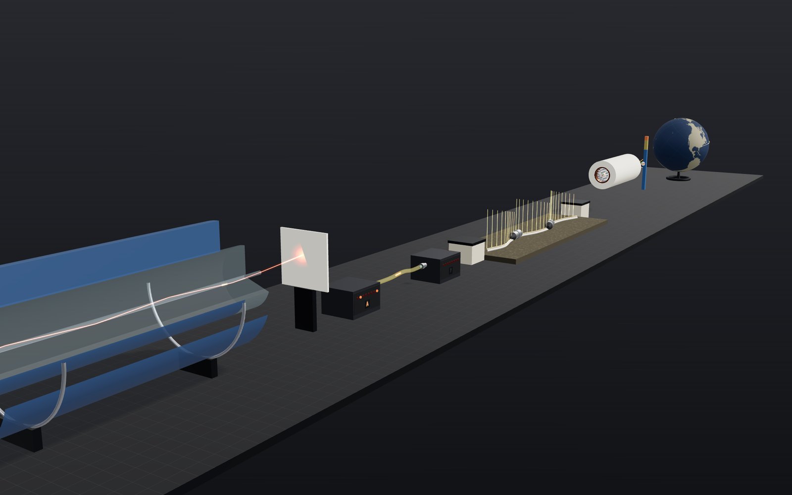
This device cannot show the 3D model. You can read the guide steps below as text.
1 / 8 A strand of glass and the cable it lives inThe bench holds five stations. On the far left a fibre is cut open to show the glass inside; on the far right a globe shows three real cable routes. The bar under the picture jumps to each station.
Drag to turn. Scroll or pinch to zoom.
A thread of glass under the ocean
When you load a web page hosted on another continent, the request almost certainly crosses the sea as flashes of infrared light inside a glass strand thinner than a hair. TeleGeography, which maps the industry, counted more than 600 active and planned submarine cables in 2026 and more than 1.5 million kilometres of cable in service. Satellite links provide another route; this exhibit does not estimate their share of international traffic.
The light in those cables has to stay inside a glass core 8.2 micrometres wide for thousands of kilometres, lose as little as possible on the way, and arrive as a clean pattern of ones and zeros. This exhibit follows it from the end of a single fibre to the bottom of the Atlantic. Each station on the bench handles one part of the problem, and the numbers in the readout come from the formulas below.
Why the light stays in the core
A beam of light crossing from one material into another changes direction. Snell's law gives the new angle:
n1 sin θ1 = n2 sin θ2
Here n is the refractive index (how much the material slows light compared with a vacuum) and θ is measured from the normal, a line drawn square to the surface. Going from a denser material into a less dense one, the beam bends away from the normal.
Now make θ1 larger and larger. The beam inside the second material swings closer and closer to the surface until, at one particular angle, sin θ2 would have to equal 1. That angle is the critical angle:
θc = arcsin(n2 / n1)
At any angle beyond it there is no solution for θ2. No light crosses the boundary at all, and the surface reflects 100% of it. Physicists call this total internal reflection. It is more efficient than any mirror, because there is no metal to absorb a fraction of the light at each bounce.
An optical fibre is built around that one effect. The core is glass with a little germanium oxide added to raise its index. The cladding around it is nearly pure silica, with a slightly lower index. A ray travelling almost parallel to the axis meets the core wall at a very shallow, grazing angle, well beyond the critical angle, and so it bounces from wall to wall for as long as the fibre goes on.
Working out the critical angle
The model uses the geometry of Corning's SMF-28e+, a standard single-mode fibre that meets ITU-T Recommendation G.652.D. The datasheet gives a core diameter of 8.2 µm, a cladding diameter of 125.0 µm, a coating diameter of 242 µm and a numerical aperture (NA) of 0.14.
For the cladding we take fused silica at 1550 nm, which has an index of 1.4440 (Malitson's measurements, via RefractiveIndex.INFO). The numerical aperture ties the two indices together:
NA = √(n1² − n2²)
so the core index is n1 = √(1.4440² + 0.14²) = 1.4508. The difference is only 0.47%, which is typical for single-mode fibre. The critical angle is then
θc = arcsin(1.4440 / 1.4508) = 84.46°
In other words, the ray has to stay within 5.54° of the fibre's axis. Outside the fibre, in air, that becomes a cone of half-angle arcsin(0.14) = 8.05°. Light aimed into the end face more steeply than 8° will not be guided.
The first slider sets the angle at the core wall. At 87° the ray is trapped: it touches the wall four times along the model and the spot on the card at the far end stays bright. Drop it to 84° and the Fresnel equations give a reflectance of only 19.6% at each bounce. At 80° the figure is 0.8%. Nearly all the light crosses into the cladding at the first bounce, travels outward at 81.7° from the normal and is absorbed by the coating, whose index is chosen to be higher than the glass so that stray light is stripped out rather than guided. The readout shows the light left at the end of the model in each case.
Turning light into ones and zeros
The simplest way to send data through a fibre is to switch the light on for a 1 and off for a 0. The transmitter in the model does exactly that with the eight bits of a capital letter. In ASCII the letter A is 65, or 01000001 in binary, so the laser flashes twice in each group of eight.
At the far end a photodiode turns each flash into a small current. The receiver checks the current at the middle of each bit period and decides whether it is above or below a threshold. The second trace in the readout shows why that works even though the received signal is weaker and its edges are rounded: as long as the ones and zeros stay clearly apart, the receiver can still tell them apart.
The speeds involved are hard to picture. At 10 gigabits per second one bit lasts 100 picoseconds. Light in the glass moves at about 204,000 km/s, so each bit occupies about 2.04 cm of fibre. A 6,600 km cable holds hundreds of millions of bits in flight at any moment.
Modern long-haul systems go much further than on and off. They change the phase and polarisation of the light as well as its brightness, and they send dozens of wavelengths through the same fibre at once (wavelength-division multiplexing). The principle is the same, though: a pattern of light that a receiver can turn back into numbers.
Losing a little light every kilometre
Even very pure glass is not perfectly clear. Tiny fluctuations in its density scatter some light sideways (Rayleigh scattering), and impurities absorb a little more. The loss is measured in decibels per kilometre. Every 10 dB cuts the power to a tenth, so 20 dB leaves 1%.
Standard single-mode fibre is specified at 0.19 to 0.20 dB/km at 1550 nm, the wavelength where silica fibre loses least. Fibre built for submarine routes is made to lose less. The third station starts at 0.17 dB/km, a representative figure for such fibre rather than a datasheet value, and its slider runs from 0.15 to 0.40 dB/km.
That sounds small until you multiply it by an ocean. Across MAREA's 6,605 km, 0.17 dB/km adds up to 1,123 dB. The light would be cut to one part in 10^112, far below a single photon. The only way across is to amplify the signal many times on the way.
Amplifiers on the seabed
Each grey pod on the model seabed is a repeater. Inside are erbium-doped fibre amplifiers: a few metres of fibre whose core contains erbium ions, pumped by a small laser. Light at 1550 nm passing through the excited erbium stimulates it to release more light at the same wavelength and phase, so the signal comes out stronger without ever being turned into an electrical signal.
The spacing is a trade-off. With amplifiers 70 km apart and 0.17 dB/km fibre, each span loses 11.9 dB, leaving 6.5% of the light, and each amplifier has to give 11.9 dB back. Stretch the spans to 120 km and the loss becomes 20.4 dB; the signal arrives so weak that the noise each amplifier adds starts to matter. Shorter spans give a cleaner signal but need more repeaters, and each one costs money and electrical power. SubCom describes a nominal spacing of 50 to 90 km for its systems. A 2024 study of Google's Dunant cable gives an average of 84 km over 6,611 km.
The repeaters need electricity, and there is no socket on the seabed. Power feed equipment at each landing station drives a constant direct current through the cable's copper conductor, with all the repeaters in series and the sea acting as the return path. SubCom's SL17 cable is rated for 15,000 volts. Its conductor has a resistance of about 1 ohm per kilometre, so the voltage needed grows with the length of the cable.
What is inside a submarine cable
The fourth station shows a cable of the SubCom SL17 type, described in detail in the Irish government's foreshore application for the AEC-2 cable. Working from the centre outward:
- Fibre tube. A small plastic tube with the fibres lying loose in a water-blocking gel.
- Strength wires. 24 high-strength steel wires in two layers (8 of 1.59 mm, then 8 of 1.50 mm alternating with 8 of 1.13 mm). They take the strain when the cable is laid or recovered and form a small pressure vessel around the fibres.
- Copper sheath. A seam-welded copper tube around the wires. It carries the power for the repeaters and seals the core against water and hydrogen, which would darken the glass over time.
- Polyethylene jacket. It insulates the copper from the sea and brings the cable to 17.0 mm. This is the lightweight (LW) cable laid on the deep ocean floor, about the width of a garden hose.
The model draws these layers to scale and steps each one back so that all of them can be seen at once.
Why cables near the shore are thicker
Down on the abyssal plain a cable is mostly left alone. Closer to land it meets anchors, fishing trawls, currents and rocks. TeleGeography, citing the International Cable Protection Committee, puts the number of cable faults at about 200 a year, and two-thirds of them come from fishing vessels and dragged anchors.
So the protection changes with depth. The SubCom selection guide used for AEC-2 puts double armour (DA) in water shallower than about 600 m: two layers of tarred galvanised steel wires, 18 and then 24 of them, each 3.35 mm thick, under tarred nylon yarn. The cable grows to 35.9 mm. Light-wire armour (LWA), with only the first layer, is used to about 2,000 m and measures 28.9 mm. Below that the 17 mm lightweight cable goes to full ocean depth. ITU-T Recommendation G.978 gives similar typical ranges: lightweight cable below 1,000 m, single armour from about 20 to 1,500 m and double armour from the shore to 100 m. In shallow water the cable is usually buried in the seabed as well.
How long light takes to cross an ocean
Light in glass is slower than in a vacuum. For a signal the speed that matters is set by the group index, which for SMF-28e+ at 1550 nm is 1.4682. So the signal moves at
v = c / 1.4682 = 299,792 / 1.4682 ≈ 204,190 km/s
roughly two-thirds of the speed of light in a vacuum. The delay along a cable of length L is simply L / v. For the three routes on the globe:
| Cable | Landing points | Length | One way | Round trip |
|---|---|---|---|---|
| MAREA (2018) | Virginia Beach to Bilbao | 6,605 km | 32.3 ms | 64.7 ms |
| Dunant (2021) | Virginia Beach to Saint-Hilaire-de-Riez | 6,400 km | 31.3 ms | 62.7 ms |
| Unity (2010) | Chikura to Redondo Beach | 9,620 km | 47.1 ms | 94.2 ms |
The cable lengths are those listed on TeleGeography's Submarine Cable Map. A cable is always longer than the straight great-circle line between its ends, because surveyors route it around steep slopes, fault zones and busy fishing grounds. Virginia Beach to Bilbao is 6,050 km along a great circle, which light in a vacuum would cover in 20.2 ms. A real connection also adds time in routers and on land at each end.
A second worked example: a wider core and its acceptance angle
The exhibit's fibre is single-mode, with a numerical aperture of 0.14. Many shorter links, such as inside a building or between two servers in a data hall, use multimode fibre, whose core is several times wider. To see how the numbers change, take a step-index glass fibre with a core index n1 = 1.480 and a cladding index n2 = 1.460. These two values are an assumption chosen to make the arithmetic clear; they do not describe any particular product.
NA = √(1.480² − 1.460²) = √(2.1904 − 2.1316) = √0.0588 = 0.2425
θc = arcsin(1.460 / 1.480) = 80.6°
A ray is guided if it meets the core wall at more than 80.6°, which means it travels within 9.4° of the axis. Seen from outside, in air, the fibre accepts a cone with a half-angle of arcsin(0.2425) = 14.0°. You can check the two numbers against each other: a ray 9.4° off axis inside the glass leaves the end face at sin θ = 1.480 × sin 9.4° = 0.242, which is the same 0.2425 within rounding.
Compare that with the exhibit's fibre, where the acceptance half-angle is only 8.05°. A wider acceptance cone makes it easier to couple light in from a cheap source. It also lets more different paths exist inside the core, and the next section shows why that costs speed.
Why pulses spread: modal and chromatic dispersion
A pulse that starts out sharp does not stay sharp. There are two main causes.
Modal dispersion happens in multimode fibre. A ray along the axis takes the shortest route. A ray bouncing at the steepest guided angle takes a longer zigzag, so it arrives later. With the assumed fibre above, the extra travel time per kilometre is
Δt = (n1 × L / c) × (n1 − n2) / n2 = (1.480 / 299,792 km/s) × (0.020 / 1.460) ≈ 4.94 µs × 0.0137 ≈ 67.6 ns per km
At 10 Gbit/s a bit lasts 100 ps, so after one kilometre a single flash is smeared across about 676 bit periods. A common rule of thumb says the spread should stay below roughly half a bit period, which for this fibre limits the rate to about 1 / (2 × 67.6 ns) = 7.4 Mbit/s over one kilometre. The Fiber Optic Association explains that graded-index multimode fibre lowers the core index toward the outside, allowing higher-order modes on longer routes to travel faster and reducing their arrival-time differences. Real fibres still have residual modal dispersion. A different solution for long distances is a core so narrow that only one path exists. The exhibit's 8.2 µm core does that, and that is why submarine cables use single-mode fibre.
Chromatic dispersion remains even in a single-mode fibre. The refractive index of glass depends slightly on wavelength, so the different colours inside one laser pulse travel at slightly different speeds. The dispersion D is quoted in picoseconds of spread per nanometre of spectral width per kilometre. For SMF-28e+, the Corning datasheet gives a zero-dispersion wavelength between 1304 and 1324 nm and a slope of at most 0.092 ps/(nm²·km). The usual approximation D(λ) = (S0 / 4) × (λ − λ0⁴ / λ³) with λ0 = 1313 nm (the middle of that range, my assumption) gives about 17 ps/(nm·km) at 1550 nm. That is an estimate from the datasheet's own formula inputs, not a printed specification.
Suppose the laser line is 0.1 nm wide (also an assumption). Over 100 km the pulse spreads by 17 × 0.1 × 100 = 170 ps, already longer than the 100 ps bit at 10 Gbit/s. Over MAREA's 6,605 km it would be 17 × 0.1 × 6,605 ≈ 11,200 ps, or about 112 bit periods. Because the spread is a fixed amount for a given fibre and distance, the receiver can undo it. TAT-8 worked at 1.3 µm, which sits inside the zero-dispersion window of 1304 to 1324 nm, so dispersion was small there. The price was higher loss than at 1550 nm.
A loss budget in numbers
The decibel scale turns multiplication into addition: a loss of x dB leaves 10^(−x/10) of the power. Take 0.20 dB/km, the upper end of the standard single-mode specification, and launch 1 mW (0 dBm, an assumed round figure):
| Distance | Loss | Fraction left | Power left |
|---|---|---|---|
| 10 km | 2 dB | 63% | 0.63 mW |
| 50 km | 10 dB | 10% | 100 µW |
| 100 km | 20 dB | 1% | 10 µW |
| 200 km | 40 dB | 0.01% | 0.1 µW |
These figures leave out connectors and splices, which each add some loss of their own, so a real link has less margin than the table suggests.
It helps to compare the table with the history. The Nobel Foundation says that in the 1960s only 1% of the light remained after 20 metres of glass fibre. That is 20 dB in 20 m, or 1,000 dB/km. Kao's goal was 1% left after a full kilometre, which is 20 dB/km. The Foundation also reports that today 95% remains after a kilometre, which is 10 × log10(0.95) = −0.22 dB/km. In half a century the loss fell by a factor of about 4,500.
Submarine systems then and now
TAT-8 entered service on 14 December 1988. The IEEE's milestone record lists a seabed distance of 5,846 km, 1.3 µm single-mode fibre, repeaters running at 280 Mbit/s and a capacity of 40,000 telephone circuits, ten times that of the last copper cable. The first transatlantic telephone cable, laid in 1956, had capacity for 36 simultaneous calls, according to the Nobel Foundation.
TeleGeography quotes the newer MAREA cable at a potential capacity of 224 terabits per second. Dividing by TAT-8's 280 Mbit/s repeaters gives a factor of 224 × 10¹² / 280 × 10⁶ = 800,000. TeleGeography separates potential capacity, which is what the cable could carry if its owner fitted all possible equipment at the ends, from the capacity actually lit, and the larger figure is the one the press usually quotes.
Cables differ in size as well as speed. TeleGeography lists the 131 km CeltixConnect between Ireland and the United Kingdom among the short ones and the 20,000 km Asia America Gateway among the long ones. It tracks more than 600 active and planned cables and puts the total in service at over 1.5 million km as of early 2026. Its FAQ also notes a change in who builds them: content providers such as Google, Meta, Microsoft and Amazon are now major investors, and the capacity deployed by private network operators has recently outpaced internet backbone operators.
Common misunderstandings
"The inside of the fibre is mirrored." No coating is needed. Total internal reflection comes from the step in refractive index between core and cladding, and it loses nothing at each bounce. A metal mirror would absorb part of the light every time.
"Light in a fibre travels at the speed of light." Only in a vacuum. In the glass the signal travels at c / 1.4682, about 204,190 km/s, roughly two-thirds as fast.
"Glass fibre is fragile." Thin glass looks brittle, but the Nobel Foundation notes that glass drawn into a long thread becomes strong, light and flexible, which is what allows it to be buried, pulled under water and bent around corners.
"Sharks and fish are the main danger." Fishing gear and anchors cause about two-thirds of all cable faults, according to ICPC data quoted by TeleGeography.
"A thicker cable carries more data." The deep-sea cable is 17 mm thick and the shore-end double-armour version is 35.9 mm. The extra thickness is steel wire against anchors, not extra fibre.
"A repeater turns the light into electricity and back." TAT-8's repeaters did exactly that. Modern repeaters amplify the light itself with erbium-doped fibre. Electricity only powers the pump lasers.
Try it on the screen
Each suggestion uses the names on the controls and in the readout.
- On the Fibre station, set Incidence on core wall to 84.4 and then to 84.6. The critical angle is 84.46°, so the first value is below it and the second is above. Compare Left at end.
- Stay on the same slider and go down to 70, the lowest setting, and compare the Light line with the one at 80. Think about which layer absorbs the light that escapes.
- On the Pulses station, pick the letter A and then Z. The readout lists the bits. A is 01000001 and Z is 01011010, so Z has two more 1s, so the laser flashes four times instead of two.
- On the Loss station, leave Fibre loss at 0.17 dB/km and set Amplifier spacing to 40, then 100, then 150. The readout Span loss reads 6.8, 17.0 and 25.5 dB, and Left after span falls from 20.9% to 2.0% and then 0.28%.
- Now set Fibre loss to 0.40 and the spacing to 150 km. The span loss is 60 dB and 0.0001% of the light is left. This is the reason spans on real systems are kept short when the glass is poor.
- On the Delay station, switch Cable route between the three cables and compare One way with Vacuum, straight. The gap is the price of the longer route and the slower speed in glass.
What the model leaves out
The ray picture in the fibre station is a simplification. A core 8.2 µm wide is only a few wavelengths across, and light in a single-mode fibre travels as one pattern of field (a mode) that spreads slightly into the cladding. The ray drawing is exact for wide multimode cores and gives the right critical angle and acceptance angle for this one, but it is not what the light literally does.
The light is drawn red. Real 1550 nm light is infrared and invisible.
The model stretches distances freely. The fibre segment is 625 µm long, the seabed spans are a fraction of a metre each, and the cable section is drawn at about 2.5 times the scale of the other stations. The routes on the globe are great circles between the landing points, not the surveyed paths, and the land outlines come from the Natural Earth public-domain dataset.
A short history
In January 1966 Charles Kao, working with George Hockham at Standard Telecommunication Laboratories in England, concluded that the large loss in glass fibre came from the glass and not from imperfections in the thread, and that the glass could be purified. According to the Nobel Foundation, he calculated that a fibre of the purest glass could carry light signals over 100 km, compared with about 20 m for the fibres of the 1960s. The paper, Dielectric-fibre Surface Waveguides for Optical Frequencies, appeared in the Proceedings of the IEE that year. Kao pointed to fused silica as the material. It melts at almost 2,000 °C, which is hard to control but gives the purest glass.
Corning Glass Works then made a 1 km optical fibre by chemical processes. The Nobel Foundation's popular information dates this to 1971.
TAT-8, the first transatlantic fibre-optic cable, entered service on 14 December 1988. It ran 5,846 km along the seabed between North America and Europe, used 1.3 µm single-mode fibre and repeaters running at 280 Mbit/s, and had capacity for 40,000 telephone circuits. Its repeaters still turned light into electrical signals and back. Optical amplifiers later took over that job. The Nobel Foundation counts the total of installed optical fibre today at over 1 billion km, and in 2009 it gave Kao half of the Physics prize for work that opened the way to fibre communication.
Questions
Why does the light not escape when the fibre bends?
A gentle bend changes the angle at which light meets the core wall only a little, and it stays beyond the critical angle. A sharp bend can push some rays below it, and that light leaks out. Fibre datasheets give a minimum bend radius for this reason.
What happens to light that hits the wall below the critical angle?
Part of it reflects and the rest crosses into the cladding. In the model, at 80° only 0.8% reflects at the first bounce. The escaping light reaches the coating, which absorbs it.
Why is 1550 nm used for long cables?
Silica fibre has its lowest loss near 1550 nm, and erbium-doped amplifiers work in the same band. Both facts together made it the standard window for long-distance links.
How thick is a submarine cable?
In deep water about 17 mm, the size of a garden hose. Near the shore armour wires make it thicker: 28.9 mm with one layer and 35.9 mm with two in the SubCom SL17 family.
Do sharks bite submarine cables?
A few bites have been recorded, but they are rare. According to the International Cable Protection Committee data quoted by TeleGeography, fish bites caused no faults between 2007 and 2014. Fishing and anchors cause about two-thirds of all faults.
Why not send data by satellite instead?
Cables carry far more data at a much lower cost per bit. A geostationary satellite also sits 35,786 km up, so a signal bounced off it takes about 240 ms just to go up and down once, several times longer than a trip across the Atlantic by cable.
How is the delay worked out?
Divide the cable length by the speed of the signal in glass, c / 1.4682. For MAREA that is 6,605 km ÷ 204,190 km/s = 32.3 ms one way.
What is numerical aperture?
It is the sine of the widest angle, measured in air, at which light can enter the end of the fibre and still be guided. For the exhibit's fibre NA = 0.14, a half-angle of 8.05°. For the assumed multimode example, 0.2425 gives 14.0°.
Why is single-mode fibre used for long distances?
A single-mode core allows only one path, so a pulse does not smear into a longer one from different ray paths. The assumed multimode example spreads a pulse by about 67.6 ns per kilometre, which is hopeless at 10 Gbit/s.
How much light is left after 100 km?
At 0.20 dB/km the loss is 20 dB, so 1% of the light remains. At the exhibit's 0.17 dB/km it is 17 dB, or 2.0%. This is why a real link needs amplifiers every few tens of kilometres.
Does a longer cable always mean a longer delay?
Yes, by 4.9 µs for every kilometre of glass (the inverse of 204,190 km/s). That is why the great-circle distance only sets a lower limit, and the surveyed route sets the real delay.
Terms
- Core: the central glass of a fibre, with the higher refractive index. The signal travels here.
- Cladding: the glass around the core, with a lower index.
- Refractive index (n): the speed of light in a vacuum divided by its speed in the material.
- Critical angle (θc): arcsin(n2 / n1), the angle from the normal beyond which total internal reflection happens.
- Numerical aperture (NA): √(n1² − n2²), the sine of the widest angle in air that the fibre accepts.
- Group index: the index that sets how fast a pulse, rather than a single wave crest, travels. 1.4682 for SMF-28e+ at 1550 nm.
- Decibel (dB): a ratio on a logarithmic scale. 10 dB is a factor of 10, 20 dB a factor of 100.
- Dispersion: the spreading of a pulse in time as it travels, either because rays take different paths (modal) or because colours travel at different speeds (chromatic).
- EDFA: erbium-doped fibre amplifier, which strengthens light directly without turning it into electricity.
- Repeater: a housing on the seabed that holds the amplifiers.
- LW, LWA, DA: lightweight, light-wire armoured and double armoured cable.
Sources
All links checked on 2026-10-16. Links added or re-read on 2026-10-22 are marked.
Corning, SMF-28e+ Optical Fiber Product Information (core, cladding and coating diameters, NA, group index, attenuation), hosted by FS. https://img-en.fs.com/file/datasheet/corning-smf-28eplus-33175.pdf
ITU-T, Recommendation G.652: Characteristics of a single-mode optical fibre and cable. https://www.itu.int/rec/T-REC-G.652
ITU-T, Recommendation G.978 (05/2025): Characteristics of optical fibre submarine cables (typical depths for LW, SA, DA and RA cable). https://www.itu.int/epublications/zh/publication/itu-t-g-978-2025-05-characteristics-of-optical-fibre-submarine-cables/en
RefractiveIndex.INFO, Optical constants of SiO2 (fused silica), Malitson 1965. https://refractiveindex.info/?shelf=main&book=SiO2&page=Malitson
Government of Ireland, AEC-2 foreshore application, Appendix 3-1: Cable characteristics (SubCom SL17 construction, diameters, depth guide, 15,000 V rating, repeater spacing). https://assets.gov.ie/120425/80872b53-3d40-42d0-8e8b-00f1ef7c7eda.pdf
TeleGeography, Submarine Cable Frequently Asked Questions (number of cables, kilometres in service, faults). https://www2.telegeography.com/submarine-cable-faqs-frequently-asked-questions
TeleGeography, Submarine Cable Map: MAREA. https://www.submarinecablemap.com/submarine-cable/marea
TeleGeography, Submarine Cable Map: Dunant. https://www.submarinecablemap.com/submarine-cable/dunant
TeleGeography, Submarine Cable Map: Unity. https://www.submarinecablemap.com/submarine-cable/unity
International Cable Protection Committee, About Submarine Telecommunications Cables. https://www.iscpc.org/documents?id=1753
United Nations, First Global Integrated Marine Assessment, Chapter 19: Submarine cables and pipelines. https://www.un.org/depts/los/global_reporting/WOA_RPROC/Chapter_19.pdf
arXiv 2401.16997, study of repeater spacing in SDM submarine cables (Dunant, 6,611 km, 84 km average spacing). https://arxiv.org/abs/2401.16997
Submarine Networks, Next Generation Submarine Network: Innovative Repeater Technology. https://www.submarinenetworks.com/en/nv/insights/next-generation-submarine-network-innovative-repeater-technology
The Nobel Foundation, The Nobel Prize in Physics 2009: Popular information (Kao's 1966 work, the 1970 Corning fibre). https://www.nobelprize.org/prizes/physics/2009/popular-information/ (checked 17 October 2026)
Georgia State University, HyperPhysics, Total Internal Reflection. http://hyperphysics.phy-astr.gsu.edu/hbase/phyopt/totint.html (checked 17 October 2026)
RP Photonics Encyclopedia, Numerical aperture. https://www.rp-photonics.com/numerical_aperture.html
The Nobel Foundation, Press release: The Nobel Prize in Physics 2009. https://www.nobelprize.org/prizes/physics/2009/press-release/
IEEE / ETHW, Milestones: Trans-Atlantic Telephone Fiber-Optic Submarine Cable (TAT-8), 1988. https://ethw.org/Milestones:Trans-Atlantic_Telephone_Fiber-Optic_Submarine_Cable_(TAT-8),_1988
Natural Earth, 1:110m land (public domain outlines on the globe). https://www.naturalearthdata.com/downloads/110m-physical-vectors/110m-land/
RP Photonics Encyclopedia, Chromatic dispersion (units of ps/(nm·km) and what they mean). https://www.rp-photonics.com/chromatic_dispersion.html (checked 22 October 2026)
RP Photonics Encyclopedia, Erbium-doped fiber amplifiers (how pumped erbium fibre amplifies the 1.5 µm band). https://www.rp-photonics.com/erbium_doped_fiber_amplifiers.html (checked 22 October 2026)
Corning, SMF-28e+ datasheet, re-read on 22 October 2026 for the zero-dispersion wavelength (1304 to 1324 nm) and slope (at most 0.092 ps/(nm²·km)). https://img-en.fs.com/file/datasheet/corning-smf-28eplus-33175.pdf
Fiber Optic Association, Optical Fiber, sections Graded Index Multimode Fiber and Bandwidth: radial index profile and reduction, not elimination, of modal dispersion. https://www.thefoa.org/tech/ref/basic/fiber.html (2026-10-23)
More exhibits
How film cameras and instant cameras work
At 1/1000 of a second a camera shutter never uncovers the whole frame at once: a narrow slit sweeps across the film instead.
Travelling at the speed of light
Light goes round the equator 7.5 times in a second, yet the same light needs 2.5 million years to reach the Andromeda galaxy.
Animal vision: see the world through 69 animals’ eyes
A red ball on green grass is easy for you to find and surprisingly hard for a dog. A honeybee sees a pattern in the same flower that you cannot.
Light and colour, from prisms to polarisers
A glass prism bends violet light about 1.6 degrees more than red, and that small gap is all it takes to spread white light into a spectrum.
Movable type and the printing press
A piece of type carries its letter back to front. Ink it, press paper on it, turn the sheet over, and the letter reads the right way round.
How a typewriter works: inside a manual typewriter
On a pica typewriter every letter, space and full stop moves the carriage the same 2.54 mm to the left.