FIG. 39How It Works
Pulley and hydraulic jack simulator: lift a crate and a car
A 50 kg crate can be lifted with an 82 N pull, as long as you are willing to pull six metres of rope for every metre it rises.
This device cannot show the 3D model. You can read the guide steps below as text.
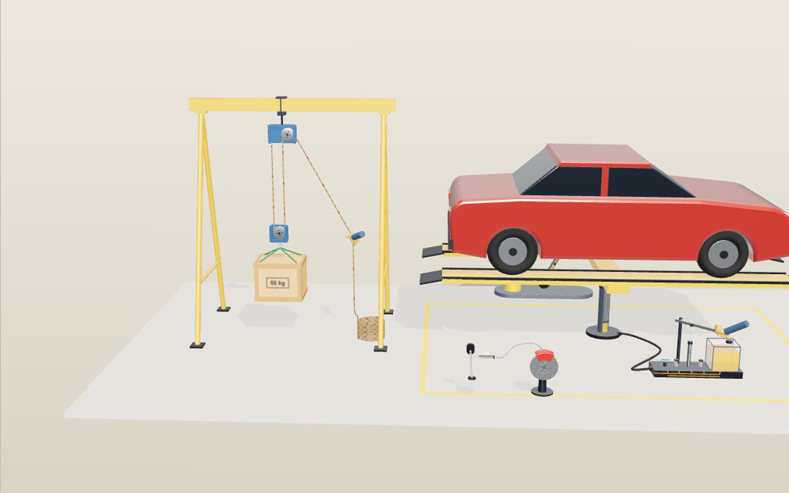
1 / 11 A workshop with two ways to liftOn the left a 50 kg crate hangs from a rope and pulleys. On the right a 1,200 kg car stands on a hydraulic lift. The panel in the corner shows force and distance for both, and you can drag the hand on the rope down to lift the crate.
Drag to turn. Scroll or pinch to zoom.
What the model shows
Try to lift a 50 kg sack of cement off the floor and you will feel every one of its 490 newtons. A builder with a rope and a few pulleys can raise the same load with a pull you could manage with one hand, and a mechanic can raise a whole car by pumping a small handle. Neither of them gets something for nothing. Both trade force for distance, and this exhibit puts numbers on that trade.
The workshop floor is drawn at full size, in metres. On the left a 50 kg pine crate hangs from a steel gantry on a block and tackle. The "Rope parts" slider reeves the same rope six ways, from a single fixed pulley to blocks with three sheaves each, giving one to six rope parts holding the crate. For the odd counts the rope end is tied to the moving block. The rope is a real tube in the model. It wraps every sheave, it never changes length, and the rope that leaves the blocks passes through the hand and piles up in a coil on the floor. Red tracer marks every 0.4 m let you follow it.
On the right a 1,200 kg car stands on a lift raised by a single hydraulic ram. A hand works a pump lever beside it. The pump cylinder, both check valves and the ram are cut open so you can see the balls move and the oil level change. The panel in the corner reports the force and the distance on both sides, worked out from the model's actual sizes.
Why a fixed pulley only changes direction
Start with one pulley bolted to the beam and the rope tied straight to the crate. The rope runs up, over the sheave and down to your hand. If the sheave turns freely, the tension is the same on both sides of it, because nothing is there to make one side pull harder than the other. The crate hangs on one rope part, so that part carries the whole weight: 50 kg × 9.81 m/s² = 490.5 N. Your hand pulls with 490.5 N too.
What you gain is direction. Pulling down is easier than lifting up, because you can hang your own body weight on the rope. The crate also rises exactly as fast as the rope moves. Pull 1 m of rope and the crate goes up 1 m. In the model the first step shows this case, with a single rope part numbered 1.
The moving pulley and counting rope parts
Now hang a second pulley on the crate. Tie the rope to the fixed block, run it down under the moving pulley, back up over the fixed pulley and down to your hand. Look at the moving pulley and everything hanging from it. Two rope parts hold it up, and each carries the same tension, so each needs only half the weight: 245 N. The rope part in your hand is the same rope, so your pull is also 245 N.
That gives the rule for any block and tackle. Count the rope parts that hold up the moving block. If there are n of them, and the sheaves turn freely, the pull is the weight divided by n. Engineers call n the ideal mechanical advantage. The model's blocks with two sheaves above and two below give four parts and a pull of 123 N; three and three give six parts and 82 N. The little blue numbers on the rope count the parts for you. The extra sheave on the fixed block that brings the rope down to your hand does not add to the count, because it is not holding the crate.
Force times distance: the rope you pay with
The price shows up at the hand. When the crate rises 0.5 m, every one of the six rope parts gets 0.5 m shorter. That 3 m of rope has to go somewhere, and it comes out through your hand into the coil. In general, the rope pulled is n times the height gained. The model's "rope pulled" figure is that product, and the coil on the floor grows by the same amount.
Multiply force by distance and the two sides agree. With four parts and a 0.5 m lift, the hand pulls 122.6 N through 2 m, which is 245 J of work. The crate gains 490.5 N × 0.5 m = 245 J of potential energy. The pulleys move the work around; they cannot add to it. This is the same rule that governs a lever or a gear train, and the readout prints both sides so you can see them match whenever friction is switched off. With friction off, the model ignores two more things: the weight of the moving block and the weight of the rope.
Friction, and why tackles stop at about six parts
Real sheaves rub on their pins, and the rope has to bend around each one. Each time the rope passes a sheave on the way to the hand, its tension must rise a little to pay for that. The model's "Sheave friction" switch assumes each sheave passes on 95% of the tension. Starting from the dead end and working toward the hand, the six rope parts then carry slightly different tensions, and the pull becomes the weight divided by 0.95 + 0.95² + … + 0.95⁶ = 5.03 instead of by 6. The pull rises from 82 N to 97 N. Work in is still force times rope pulled, but now only 84% of it reaches the crate; the rest turns into heat in the bearings and the rope.
Adding sheaves keeps helping, but less each time. With 5% lost per sheave, the sum can never exceed 0.95 ÷ 0.05 = 19, so no tackle of this kind can bring the 490 N crate below about 26 N, however many sheaves you hang. Long before that point the rope to be pulled becomes absurd: a 19-part tackle needs 19 m of rope for each metre of lift. That is why most hand tackles stop at four to six parts, and why big cranes use winches and drums instead of more sheaves.
Pascal's principle in a closed box of oil
A hydraulic jack makes the same trade with a liquid. Oil barely squeezes, so pushing on it at one point raises the pressure everywhere in a sealed system by the same amount. This is Pascal's principle. Pressure is force per area, so the same pressure acting on a bigger area makes a bigger force.
In the model the small piston is 20 mm across and the ram 120 mm across. Area goes with the square of the diameter, so the ram has (120 ÷ 20)² = 36 times the area. The car weighs 1,200 kg × 9.81 = 11,772 N. Spread over the ram's 0.0113 m², that needs a pressure of 1.04 MPa, about ten times atmospheric pressure. The same 1.04 MPa on the small piston's 0.000314 m² takes only 327 N.
Distance pays again. Each 50 mm press of the small piston pushes 15.7 cm³ of oil into the ram cylinder. Spread over 36 times the area, that oil lifts the ram 50 ÷ 36 = 1.39 mm. Work in per stroke is 327 N × 0.05 m = 16.4 J, and the car gains 11,772 N × 0.00139 m = 16.4 J. Raising the car 0.3 m takes 216 strokes.
Inside the jack: plunger, two check valves and a release valve
A single push would only lift the car 1.39 mm, so the pump has to refill and push again, and the oil must not run back in between. Two check valves handle this. Each is a ball pressed onto a round seat by a small spring. Oil pushing from the seat side lifts the ball and flows past it; oil pushing the other way only presses the ball harder onto its seat.
When you lift the lever, the plunger rises and the pressure in the pump chamber drops. The inlet valve opens and oil flows in from the tank, while the outlet valve stays shut because the high pressure on the ram side holds its ball down. When you press the lever, the chamber pressure climbs above the ram pressure. The inlet ball slams shut, the outlet ball lifts, and oil goes to the ram. In the model the oil passage glows during each half of the stroke, and the balls rise off their seats.
The lever multiplies force once more before the oil does. The hand grips the lever 0.5 m from the pivot and the plunger is linked 0.1 m from it, so the hand needs only 327 ÷ 5 = 65 N, about what it takes to hold a 6.7 kg bag. The release valve is the third valve. Opening it connects the ram to the tank, and the car's weight pushes the oil back. Turn it on in the controls and the car settles at a steady rate while the tank refills.
The numbers for the car
The piston sliders show how the design choices pull against each other. Make the small piston 40 mm and the ram 60 mm and the area ratio falls to 2.25. Each stroke now lifts the car 22 mm, but the small piston needs 5,232 N and the hand at the lever 1,046 N, more than a person can push. Go the other way, a 10 mm plunger under a 200 mm ram, and the ratio is 400. The hand needs less than 6 N, but each stroke lifts the car 0.125 mm and 0.3 m takes 2,400 strokes. Real hand jacks pick ratios between these, with a long lever, so a person can lift a car in a minute or two of pumping.
Pressure is the number that sets the size of everything else. At 1.04 MPa the model's oil is gentle; a small bottle jack with a 30 mm ram holding a tonne works at more than ten times that, which is why jack cylinders are thick-walled steel.
Worked example: the same car lifted two ways
Take the 1,200 kg car from the exhibit. It weighs 11,772 N, and raising it 0.3 m means giving it 11,772 × 0.3 = 3,532 J of potential energy. Any machine that does this has to take in at least that much work. The two machines below differ only in how they spread it over force and distance.
First the block and tackle. This is an assumption, because the exhibit hangs only the 50 kg crate on it: scale the six-part rig up to the car, with a rope strong enough and the same 5% loss per sheave. With no friction the pull is 11,772 ÷ 6 = 1,962 N, the weight of a 200 kg mass. The rope pulled is 6 × 0.3 = 1.8 m, so the hand does 1,962 × 1.8 = 3,532 J. Turn the friction on and the divisor becomes 5.03, so the pull is 11,772 ÷ 5.03 = 2,339 N, and the hand does 2,339 × 1.8 = 4,210 J. Of that, 3,532 ÷ 4,210 = 84% reaches the car.
Now the jack with its default sizes. The hand needs 65 N, and each stroke of the lever moves the hand 5 × 0.05 = 0.25 m while the car rises 1.39 mm. Raising it 0.3 m takes 216 strokes, so the hand travels 216 × 0.25 = 54 m and does 65.4 × 54 = 3,532 J. The energy is the same as for the tackle. Only the shape of the bill is different: 65 N over 54 m instead of 1,962 N over 1.8 m.
The jack hides a neat rule. For any pair of piston sizes, the hand force multiplied by the number of strokes needed for 0.3 m comes out at 14,126 N. A 24 mm plunger under a 120 mm ram has an area ratio of 25, so the hand needs 94 N for 150 strokes. A 14 mm plunger under a 140 mm ram has a ratio of 100, so the hand needs 23.5 N for 600 strokes. Both multiply out to 14,126. Choosing piston sizes only decides where on that line the jack sits: easy pushes and many strokes, or hard pushes and few.
Why friction compounds: the capstan rule
The model's flat 5% per sheave is a simplification worth looking at. A rope lying against a curved surface presses on it, and the friction that results is proportional to that pressure. Working it out for a short piece of rope and adding up the pieces gives a clean result, often called the capstan equation: the tension on the heavy side is at most the tension on the light side times e raised to μθ, where μ is the friction coefficient and θ is the angle the rope wraps around, in radians. A derivation of it is part of MIT's course notes on modeling dynamic systems.
The exponent explains two things at once. A sheave that turns on a good bearing stays far from this limit, because the rope rolls on the groove instead of sliding on it, and only the bearing friction and the bending of the rope are left. The model's 5% is a stand-in for those. And in a tackle, the losses multiply from one sheave to the next, which is why the sum in the earlier section is a geometric series.
A sailor's capstan shows the other side of the same equation. Assume μ = 0.3 between a rope and a stationary drum and two full turns, so θ = 4π = 12.57 rad. The factor is e^3.77 = 43. A sailor holding the loose end with 100 N can hold 4,300 N on the other. Nothing is rotating the drum in this case. The rope would slip if the pull went higher, but the friction does the holding. The tackle uses the opposite trade: it wants the friction as small as possible and loses 5% each time.
Cranes, elevators, excavators and brakes
Roman construction cranes. A relief from the tomb of the Haterii, a family of builders who worked on the Colosseum, is now in the Vatican Museums. On the left it shows a crane driven by a large wheel worked by people. Vitruvius describes the same family of machines in Book 10, from the three-pulley trispastos up to the polyspaston. A walking wheel turns a drum, the drum winds the rope, and the pulley block divides the load again before it reaches the stone, so the two multiplications add up. The builders paid in distance as well: every metre the block rose took n metres of rope.
Hydraulic cranes. In 1846 William Armstrong put up the first hydraulic crane on the Newcastle quayside to unload coal, after the town water scheme of 1845 gave him the pressure to use. It ran on the excess pressure in the town's water supply. This is Pascal's principle used for a purpose very unlike a car jack: the pressure comes from outside and a piston at the crane turns it into a pull.
Elevators. Most elevator cars hang from steel ropes over a drive sheave, with a counterweight on the other side. Suppose, as an assumption, a car of 1,000 kg, a rated load of 800 kg and a counterweight of 1,400 kg, which is the car plus half the load. With a full car the motor holds up 1,800 − 1,400 = 400 kg of imbalance. With an empty car it holds 1,400 − 1,000 = 400 kg the other way. Without the counterweight the motor would have to carry the car's whole weight, up to 1,800 kg, on every trip. The National Academy of Engineering's account of elevator history says the first counterweight did not appear before 1670, and that counterweights and two-to-one roping lower the power needed. Two-to-one roping is the n = 2 case of this exhibit: the car moves at half the speed of the rope and the rope carries half the car's weight. Elisha Otis showed his safety brake at the 1854 New York World's Fair by having the rope cut with an axe while he stood on the platform, according to ASME and the National Inventors Hall of Fame. The brake did not change the mechanical advantage at all. It made the machine safe enough for people.
Excavators. A 22.6-tonne excavator data sheet from one manufacturer, SANY, gives a relief valve setting of 34.3 MPa for the implement circuits and a boom cylinder with a 120 mm bore. That bore is the same as the ram in this exhibit. The pressure is 34.3 ÷ 1.04 = 33 times higher, so the push at the relief setting can reach 34.3 MPa × 0.01131 m² = 388 kN, against 11.8 kN for the model's ram. This is an upper limit set by the relief valve, not the force the boom delivers: the arm geometry, the other cylinders and the pump flow all decide what ends up at the bucket. It does show why excavators use hydraulics: a pressure 33 times higher packs that much force into a cylinder the size of this exhibit's ram.
Car brakes. OpenStax works through a brake example. The driver presses with 100 N, a lever raises that to 500 N on a pedal cylinder with a 5 mm bore, and each of four wheel cylinders has a 25 mm bore. The area ratio is (25 ÷ 5)² = 25, so each wheel cylinder pushes with 12,500 N. The oil that one wheel cylinder takes in comes from the pedal cylinder, so the pedal cylinder piston has to travel 25 times as far as the wheel piston, and with four wheels sharing the oil it moves 100 times as far as each. OpenStax adds that power brakes have a motorized pump that does most of the work. The example therefore covers only the multiplication between pedal and wheel.
Odd numbers of rope parts
The count of rope parts holding the load does not have to be even. If the dead end is tied to the upper block, the rope always runs down and up in pairs, and the count comes out 2, 4 or 6. Tie the dead end to the moving block instead, at a small eye called the becket, and that first stretch of rope also holds the load. Two sheaves above and one below then give three parts, and three above with two below give five. Vitruvius used exactly these two names: the trispastos for three pulleys and the pentaspastos for five.
Choose 3 or 5 on the pulley bench and count the numbered parts. With no friction the pull is 490.5 ÷ 3 = 164 N and 490.5 ÷ 5 = 98 N, and the rope pulled is three or five times the lift. The model checks the drawn rope: raising the lower block by 0.5 m shortens the path from the dead end to the hand by exactly 1.5 m or 2.5 m. Rigging books use the same trick when they turn a block upside down to gain one part: the side that the hauling part leaves from, fixed or moving, decides whether it adds to the count.
The differential chain hoist
A tackle with many parts needs a lot of rope. Thomas Aldridge Weston found a way around that with two chain wheels of slightly different size fixed to one axle and a single endless chain. One loop of the chain hangs down around a sheave that carries the hook; the other loop hangs free for the hand. Each turn of the axle winds one big circumference of chain onto the large wheel and lets out one small circumference from the small wheel, so the load loop shortens by the difference and the hook rises by half of it. The mechanical advantage is 2R ÷ (R − r).
The model uses chain wheels with 10 and 9 pockets, so the advantage is 2 × 10 ÷ 1 = 20 and 200 kg needs only about 98 N on the hand chain when nothing is lost. The cost is distance again: 20 m of hand chain for each metre of lift. The 10 and 8 wheels give 10, and 15 and 14 give 30.
The Powerhouse collection in Sydney holds a two ton block of this kind made by Tangyes of Birmingham. Its notes describe how the Tangye brothers developed a pitch chain so the links seated cleanly in the pockets, showed the block in five sizes from 10 cwt to 3 tons at the 1862 International Exhibition, and sold about 3,000 sets in nine months.
Chain hoists are slow and lossy, and that is part of their appeal. In the model each pass round the lower sheave and the axle keeps 95% of the force. The 10 and 9 block then lifts at 49% efficiency, and below about 50% a machine of this kind will not run backwards under its load. Let go of the hand chain and the load stays where it is.
What real pulleys lose
The 5% loss in the model is not a guess. Petzl, a maker of rope access and rescue equipment, prints an efficiency for each pulley. The RESCUE M and SPIN L1, with 38 mm sheaves on sealed ball bearings, are rated at 95%. The small FIXE, with a 21 mm sheave on self lubricating bushings, is rated at 71%: only 71% of the pull comes out on the far side.
That difference grows quickly. With FIXE pulleys four rope parts divide the weight by 0.71 + 0.71² + 0.71³ + 0.71⁴ = 1.83, so the pull is still more than half of what a single frictionless pulley would need. Five parts reach 2.006, and six only 2.13, because the sum can never pass 0.71 ÷ 0.29 = 2.45. Rescue teams therefore use few, efficient pulleys rather than many cheap ones. Set the pulley bench to the FIXE type and watch the bars flatten after three parts.
Inside an excavator boom cylinder
Behind the car lift a double acting cylinder lifts a boom. Its bore, 120 mm, stroke, 1,285 mm, and relief valve setting, 34.3 MPa, come from the SANY SY215C data sheet; the bench is drawn at 0.45 scale and its geometry is a model. Oil enters the cap end to push the piston out. To pull it back the pump feeds the rod end, where the rod takes up part of the area, so the same pressure pulls with less force but moves the rod faster.
The pressure is set by the load, not by the pump. With 3,000 kg on the tip and the cylinder 0.6 m out, the cylinder has to push about 105 kN and the oil sits near 9.3 MPa. Put 12,000 kg on the tip and the pressure needed would pass 34.3 MPa; the relief valve opens, the oil goes back to the tank and nothing rises. The pump decides only the speed: one pump at 222 L/min would push a 120 mm piston out at 0.33 m/s.
The same rule sets the size of industrial cylinders. Enerpac lists a double acting cylinder, the BRD256, with a 63.5 mm bore and a 47.8 mm plunger. At its rated 700 bar it pushes 222 kN and pulls only 98 kN, because the effective area drops from 31.7 cm² to 13.7 cm² on the return side.
The brake circuit on the bench
At the front of the floor a brake circuit uses the OpenStax worked example. A 100 N push on the pedal becomes 500 N on the pedal cylinder through a 5 to 1 lever. The pedal cylinder is 5 mm across and the caliper piston 25 mm, so the line pressure is about 25.5 MPa and the caliper piston squeezes with 12,500 N. The pedal cylinder piston must travel 25 times as far as the caliper piston; with four wheels drawing on the same oil it would be 100 times.
Press "Spin the wheel to 50 km/h" and set a pedal force. The pad friction coefficient of 0.4, the pad radius of 0.11 m and the wheel inertia are model values chosen to give sensible stopping distances, so the number of turns is an illustration. At 100 N the wheel needs about 4.2 turns to stop, and at 250 N about 1.7.
Where the machine list gets its numbers
Every entry in "Machines that lift" names one source, and the figures on its card are the ones that source gives: Petzl product pages for pulley efficiency, the Powerhouse collection for the Weston block, the SANY data sheet for cylinder sizes and pressures, the Enerpac catalogue for the BRD256, the NASA fact sheet for the crawler transporter, ASME landmark papers for the 50,000 ton press, the Canal and River Trust for the Anderton Boat Lift, Scottish Canals for the Falkirk Wheel, the Tower Bridge site for its hydraulic engines and the FAA maintenance handbook for aircraft pressures. Cards marked "worked out from the source figures" combine those numbers, for example 16 cylinders of 23 inch bore at 3,000 psi on the NASA crawler give about 19.9 million pounds of force, and those sums are checked in the exhibit's own test file.
Common misunderstandings
- "A pulley makes the load lighter." The crate still weighs 490.5 N. What changes is how many rope parts share it. Each part carries 490.5 ÷ n N when the sheaves are free, and the hand has to move the rope n times as far.
- "Count every wheel in the block." Count the rope parts that hold the moving block up. A sheave that only turns the rope toward your hand adds friction and adds nothing to the count, as with the extra sheave on the fixed block.
- "Twenty pulleys beat six." With 5% lost per sheave the divisor can never pass 19, and each extra sheave adds less than the one before. At six parts the model already gets 5.03 out of a possible 6. Beyond that, the extra rope to haul and the extra things to inspect are a real cost.
- "The big piston has more pressure." The pressure is the same at both pistons, 1.04 MPa with the default sizes. The big one has more force because it has more area.
- "The jack makes extra energy." One stroke puts in 16.4 J at the plunger and the car gains 16.4 J. In a real jack some of it leaves as heat in the seals and the oil, so a little less arrives.
- "Pascal's principle is the only multiplier in a jack." There are two. The lever gives 5, the pistons give 36, so the hand's push reaches the car 180 times larger: 11,772 N ÷ 65.4 N = 180.
- "Hydraulic means oil under high pressure." The default jack runs at 1.04 MPa. Set "Small piston" to 10 mm and "Large piston" to 100 mm and the pressure rises to 1.50 MPa. Set 20 mm and 200 mm and it falls to 0.37 MPa, though the force on the car is the same 11,772 N in both cases. Pressure depends on the load and the ram area, not on how hard anyone pumps.
Try it on the screen
- Set "Rope parts" to its first position and "Crate height" to 0.5 m. The panel reads pull 490.5 N and rope pulled 0.5 m. Move through 2, 4 and 6 parts and watch the pull fall to 245, 123 and 82 N while the rope pulled rises to 1, 2 and 3 m.
- At each setting multiply the pull by the rope pulled. It comes to 245 J every time while "Sheave friction" is off, and the panel's work and efficiency lines agree.
- Turn "Sheave friction" on and step back through the settings. The pull should read about 516, 265, 139 and 97 N, with efficiencies of 95, 93, 88 and 84%. At 1 part the pull is 490.5 ÷ 0.95.
- Open "Part names" and find the blue numbers on the rope. Count the parts that run down to the moving block and compare with the slider.
- Leave "Small piston" at 20 mm and "Large piston" at 120 mm. The panel gives an area ratio of 36, an oil pressure of 1.04 MPa, 327 N on the small piston and 65 N at the lever end. Click the pump lever once and the car rises by about 1.4 mm.
- Set "Car height" to 0.3 m and read the strokes line: 216. Then change "Small piston" to 40 mm and "Large piston" to 60 mm. The area ratio is 2.25 and the lever end now needs about 1,046 N, which the panel marks as too hard for one person. Try 10 mm and 200 mm instead: about 6 N, but 2,400 strokes.
- Find a pair of sizes where the lever end needs under 30 N, such as 14 mm and 140 mm. Read the strokes line for 0.3 m. Then look for a pair that is easy to push and takes few strokes. There is none: force times strokes stays at 14,126.
- Turn on "Release valve" with the car raised. The car comes down at a steady rate and the oil level in the tank rises.
Where the model is simpler than the real thing
Real blocks put their sheaves side by side on one pin, so the rope parts bunch together and are hard to count. The model spreads the sheaves out along the beam so each part hangs on its own. The force and length rules do not depend on that layout.
The model treats the rope as unstretchable and perfectly flexible, and it leaves out the weight of the moving block, the rope, the lift platform and the ram. The friction switch uses one flat 5% loss per sheave; real losses depend on the bearing, the rope's stiffness and how sharply it bends. On the hydraulic side the oil is treated as incompressible and leak-free, the seals have no friction and the weight of the oil itself is ignored, so the pressure is the same at every height. A real lift also needs a safety lock so the car never rests on the oil alone.
From Archimedes to Bramah
Pulley tackles are very old. In the first century BC the Roman engineer Vitruvius described, in Book 10 of his work on architecture, hoisting machines by the number of pulleys in their blocks, a block of three being the trispastos and a machine with many pulleys the polyspaston.
The best known pulley story is about Archimedes, and it comes from Plutarch's Life of Marcellus, written about 300 years after Archimedes died in 212 BC. Plutarch says Archimedes told King Hiero of Syracuse that any given weight could be moved by any given force, and that if there were another world he could go to, he could move this one. Asked for a demonstration, he took a three-masted merchant ship that had been hauled ashore by many men, loaded it with passengers and freight, and, sitting at a distance, drew it toward himself with a system of compound pulleys. It is a story told long after the fact, not an eyewitness report, but it shows the idea was already linked to his name.
Blaise Pascal worked out the hydraulic principle in his treatise on the equilibrium of liquids, finished by about 1654 and printed in 1663, a year after his death. Pressure in a closed liquid can multiply force, and Pascal is usually credited with the idea of the hydraulic press for that reason. Turning the idea into a working machine needed seals that could hold high pressure. Joseph Bramah, the London locksmith, patented the hydraulic press in 1795, and the same arrangement, a small pump piston and a large ram joined by oil, is the heart of every hand-pumped jack today.
How the numbers were checked
The readout uses W = mg with g = 9.81 m/s², F = W ÷ n for ideal tackles and F = W ÷ (e + e² + … + eⁿ) with e = 0.95 for the friction case, rope pulled = n × h, the chain hoist advantage 2R ÷ (R − r), p = W ÷ A₂, F₁ = p × A₁ and rise per stroke = 50 mm × A₁ ÷ A₂. These agree with hand values, and the rope path drawn in the model confirms that lifting the moving block by 0.5 m feeds exactly n × 0.5 m of rope through the hand.
Questions
Does a pulley reduce the work needed to lift something?
No. An ideal pulley system reduces the force and increases the rope you have to pull by the same factor, so force times distance stays equal to the weight times the height. Friction makes the work at the hand a little larger than the work done on the load.
How do I find the mechanical advantage of a block and tackle?
Count the rope parts that hold up the moving block, including the one tied to it if the dead end is on the moving block. Without friction, the pull equals the weight divided by that number. A part that only runs from the fixed block to your hand does not count.
Why does a single fixed pulley not make lifting easier?
It holds the load on one rope part, so the pull equals the weight. It still helps because you can pull down with your body weight and stand clear of the load, but it gives no force advantage.
Why not use twenty pulleys and lift a car by hand?
Friction grows with every sheave. At 5% loss per sheave the force can never drop below about 1/19 of the weight, and you would have to pull twenty metres of rope for each metre of lift. Winches and hydraulics do the job with far less rope.
What does Pascal's principle actually say?
A change in pressure applied to a confined fluid that does not compress is passed on equally to every part of the fluid and to the walls of its container. In a jack this means the small piston and the ram feel the same pressure.
Why does a hydraulic jack need check valves?
The pump piston only moves a little oil per stroke, so it has to refill and push many times. The inlet check valve lets oil in from the tank on the up-stroke, and the outlet check valve lets it out to the ram on the down-stroke while stopping it from flowing back between strokes.
How does the car come down again?
Opening the release valve connects the ram cylinder to the tank. The car's weight pushes the oil back through the valve, and the narrow passage keeps the descent slow.
How much does the pump lever add to a hydraulic jack?
It adds a factor of 5 in the model, because the hand sits 0.5 m from the pivot and the plunger 0.1 m. The oil then adds the area ratio, 36 with the default sizes. Together the hand's push reaches the car multiplied by 180, so 65 N at the lever end holds up 11,772 N.
Why do elevators have a counterweight?
The counterweight hangs on the other end of the rope and balances most of the car, so the motor only handles the difference. In the example above, a 1,400 kg counterweight leaves the motor with 400 kg of imbalance whether the car is full or empty, instead of up to 1,800 kg.
Why does an excavator run at a much higher oil pressure than a car jack?
Pressure lets a given cylinder push harder. One manufacturer's data sheet for a 22.6-tonne excavator lists a relief setting of 34.3 MPa, about 33 times the exhibit's 1.04 MPa, which lets a 120 mm cylinder push with up to 388 kN. The price is thicker walls, stronger seals and a pump that can supply that pressure.
Can friction ever help in a rope system?
Yes, when the aim is to hold something. A rope wrapped around a fixed drum can hold a force that grows with e raised to μθ, so two turns at μ = 0.3 let 100 N hold about 4,300 N. A block and tackle wants the opposite, because every bit of friction there is lost work.
Why does an odd number of rope parts tie the rope to the moving block?
Because each rope part that runs between the blocks holds the load, and the dead end counts as a part only when it hangs from the moving block. Tied above, the dead end carries nothing to the crate and the parts come in pairs. Tied to the becket of the lower block, it adds one more.
Why does a chain hoist not drop the load when you let go?
Its friction is large compared with its advantage. In the model the 10 and 9 block lifts at 49% efficiency, and a machine below about 50% cannot be driven backwards by its own load, so the hook stays put until someone pulls the other side of the hand chain.
Why does a double acting cylinder pull with less force than it pushes?
On the push stroke the oil presses on the whole piston. On the return stroke it presses only on the ring around the rod. The Enerpac BRD256 shows the effect: 31.7 cm² and 222 kN going out, 13.7 cm² and 98 kN coming back at the same 700 bar.
Terms
- Sheave: the grooved wheel inside a pulley block.
- Block: a frame holding one or more sheaves on a pin.
- Block and tackle: two blocks with a rope reeved between them.
- Rope part: one stretch of rope between the two blocks.
- Dead end: the end of the rope that is tied to a block and does not move through it.
- Mechanical advantage: load divided by the force needed to move it.
- Pascal's principle: pressure applied to a confined liquid acts equally throughout it.
- Ram: the large piston of a hydraulic jack or press.
- Check valve: a valve that lets fluid flow one way only.
- Release valve: the valve that lets oil return from the ram to the tank.
- Becket: an eye on a block where the dead end of the rope is tied.
- Differential pulley: a chain hoist with two wheels of different size on one axle.
- Double acting cylinder: a cylinder that oil can push in both directions.
- Relief valve: a valve that opens above a set pressure and returns oil to the tank.
Sources
- Plutarch, Life of Marcellus, chapter 14 (Archimedes, Hiero and the ship moved with compound pulleys), Loeb translation on LacusCurtius. https://penelope.uchicago.edu/Thayer/E/Roman/Texts/Plutarch/Lives/Marcellus*.html (checked 2026-10-16)
- Vitruvius, De Architectura, Book X, chapter 2 (trispastos, pentaspastos, polyspaston), on LacusCurtius. https://penelope.uchicago.edu/Thayer/E/Roman/Texts/Vitruvius/10*.html (checked 2026-10-16)
- OpenStax, College Physics 2e, 9.5 Simple Machines (pulleys and mechanical advantage). https://openstax.org/books/college-physics-2e/pages/9-5-simple-machines (checked 2026-10-17)
- OpenStax, College Physics 2e, 11.5 Pascal's Principle (hydraulic systems, force and distance). https://openstax.org/books/college-physics-2e/pages/11-5-pascals-principle (checked 2026-10-17)
- Bibliothèque nationale de France, BnF Essentiels, Traités de l'équilibre des liqueurs (reworked by 1654, published after his death in 1663). https://essentiels.bnf.fr/fr/image/fe7b941f-4b19-40f9-8834-e3821dfdb6e4-blaise-pascal-traites-equilibre-liqueurs-et-la-pesanteur-la-masse-air (checked 2026-10-17)
- The Rockefeller University, Rare Books, Pascal, Blaise (1623 to 1662; the 1663 Traité; credited with the hydraulic press). https://digitalcommons.rockefeller.edu/rare-books/129/ (checked 2026-10-17)
- NASA Glenn Research Center, Pascal's Principle and Hydraulics. https://www.grc.nasa.gov/www/k-12/WindTunnel/Activities/Pascals_principle.html (checked 2026-10-16)
- HyperPhysics, Georgia State University, Pascal's Principle. http://hyperphysics.phy-astr.gsu.edu/hbase/pasc.html (checked 2026-10-16)
- Sheffield Museums, Bramah Press (Joseph Bramah patented the hydraulic press in 1795). https://www.sheffieldmuseums.org.uk/whats-on/bramah-press/ (checked 2026-10-17)
- Vatican Museums, Mausoleum of the Haterii (relief with a crane worked by a large wheel; the family's building work in the Flavian period). https://www.museivaticani.va/content/museivaticani/en/collezioni/musei/museo-gregoriano-profano/Mausoleo-degli-Haterii.html (checked 2026-10-22)
- National Academy of Engineering, The Evolution of Elevators (Frontiers of Engineering, NCBI Bookshelf; first counterweight not before 1670; counterweights and two-to-one roping lower the power needed; Otis safety brake, 1854 demonstration). https://www.ncbi.nlm.nih.gov/books/NBK481624/ (checked 2026-10-22)
- ASME, Elisha Graves Otis (the 1854 New York Crystal Palace demonstration with the rope cut). https://www.asme.org/topics-resources/content/elisha-graves-otis (checked 2026-10-22)
- National Inventors Hall of Fame, Elisha Graves Otis (elevator brake, U.S. Patent No. 31,128). https://www.invent.org/inductees/elisha-graves-otis (checked 2026-10-22)
- MIT OpenCourseWare 2.141, N. Hogan, Capstan: a mechanical amplifier (F_out = e^(μθ) F_control for a rope on a drum). https://ocw.mit.edu/courses/2-141-modeling-and-simulation-of-dynamic-systems-fall-2006/09bbd00ad1a816a401f166e35fbaf231_capstan_amplifie.pdf (checked 2026-10-22)
- Newcastle University, Northern Innovation, William George Armstrong (the quayside crane run on surplus town water pressure). https://research.ncl.ac.uk/northerninnovation/exhibits/williamgeorgearmstrong/ (checked 2026-10-22)
- Grace's Guide to British Industrial History, William George Armstrong ("before the end of 1846 the first hydraulic crane erected was at work on the quay at Newcastle"). https://www.gracesguide.co.uk/William_George_Armstrong (checked 2026-10-27)
- SANY, Hydraulic Excavator SY215C data sheet (manufacturer data: 22,600 kg, implement circuit relief valve 34.3 MPa, boom cylinder 120 mm bore). https://www.sanyglobal.com/d/file/product/excavator-medium/2017-04-13/56aef9e9e5f97683b2b10836e2dd3f10.pdf (checked 2026-10-22)
- Petzl, FIXE pulley (21 mm sheave on bushings, efficiency 71 %, working load 5 kN). https://www.petzl.com/INT/en/Professional/Pulleys/FIXE (checked 2026-10-27)
- Petzl, RESCUE M pulley (38 mm sheave on sealed ball bearings, efficiency 95 %, working load 8 kN). https://www.petzl.com/INT/en/Professional/Pulleys/RESCUE-M (checked 2026-10-27)
- Petzl, SPIN L1 pulley (38 mm sheave, ball bearings, swivel, efficiency 95 %). https://www.petzl.com/INT/en/Professional/Pulleys/SPIN-L1 (checked 2026-10-27)
- Powerhouse Collection (Museum of Applied Arts and Sciences), Differential pulley block made by Tangyes Ltd (T. A. Weston, 2 ton; 1862 International Exhibition; jacks for the Great Eastern). https://collection.powerhouse.com.au/object/12102 (checked 2026-10-27)
- Enerpac, E330e Industrial Tools catalogue (BRD256 double acting cylinder: 63.5 mm bore, 47.8 mm plunger, 222 kN and 98 kN at 700 bar). https://vault.enerpac.com/m/5c187843574a76c0/original/Enerpac_Industrial_Tools_Catalog_E330e_EN-GB.pdf (checked 2026-10-27)
- NASA, Crawler-Transporters fact sheet (16 JEL cylinders, 23 inch bore on CT 2, JEL 3,000 psi, steering 5,000 psi, 18 million pound capacity). https://www.nasa.gov/wp-content/uploads/2021/04/combined_crawler-transporters_fact_sheet_final.pdf (checked 2026-10-27)
- ASME, Crawler Transporters of Launch Complex 39, landmark 20 (jacking, steering and automatic levelling systems). https://www.asme.org/about-asme/engineering-history/landmarks/20-crawler-transporters-of-launch-complex-39 (checked 2026-10-27)
- ASME, The Wyman-Gordon 50,000-Ton Forging Press, landmark brochure (1955, 106 million pounds). https://www.asme.org/wwwasmeorg/media/resourcefiles/aboutasme/who%20we%20are/engineering%20history/landmarks/89-wyman-gordon-50000-ton-hydraulic-forging-press.pdf (checked 2026-10-27)
- Canal and River Trust, Boat lifts (Anderton Boat Lift 1875, rams 3 feet across, tanks 252 tonnes when flooded). https://canalrivertrust.org.uk/things-to-do/canal-history/canal-heritage-and-architecture/boat-lifts (checked 2026-10-27)
- Tower Bridge, How does Tower Bridge work? (steam pumps, six accumulators, electro hydraulic since 1976). https://www.towerbridge.org.uk/stories/how-does-tower-bridge-work (checked 2026-10-27)
- Scottish Canals, The Falkirk Wheel (1,800 tonnes in balance, 35 m, 1.5 kWh per rotation). https://www.scottishcanals.co.uk/falkirk-wheel/ (checked 2026-10-27)
- FAA, Aviation Maintenance Technician Handbook, General (FAA-H-8083-30A; Pascal example of 5 lb on 0.5 square inch, ground hydraulic units up to 3,000 psi). https://www.faa.gov/sites/faa.gov/files/regulations_policies/handbooks_manuals/aviation/amt_general_handbook.pdf (checked 2026-10-27)
- Calculations on this page: W = mg, F = W ÷ n, F = W ÷ (e + e² + … + eⁿ), s = n × h, p = W ÷ A₂, F₁ = p × A₁, rise = stroke × A₁ ÷ A₂, pedal-to-wheel area ratio (D ÷ d)², capstan factor e^(μθ).
More exhibits
How windmills and watermills work
The sails of a Dutch mill are as wide as an eight-storey building is tall, and at 7 m/s they still take only about a fifth of the wind.
Why do ships float?
A 1,900-tonne steel ship floats, yet the same 1,900 tonnes of steel pressed into a cube goes straight to the bottom.
How a wing makes lift, and what changes as the angle grows
Air over the top of a wing reaches the trailing edge first. It does not wait for the air underneath.
Billiards angles: aiming, spin and the diamond system, step by step
Two equal balls that meet without spin part at a right angle, and a ball struck at its centre slides for 12/49 of v²/μg before it starts to roll.
Why a spinning gyroscope doesn’t fall over
A wheel spinning at 3,000 rpm can rest one end of its axle on a post with nothing under the other end, and it circles the post once every 2.8 seconds.
Roller coaster physics: how roller coasters work
A train that creeps over a 42 m lift hill at 3 m/s is doing 99 km/h at the bottom, and nothing but gravity has pushed it.