FIG. 46How It Works
Why a spinning gyroscope doesn’t fall over
A wheel spinning at 3,000 rpm can rest one end of its axle on a post with nothing under the other end, and it circles the post once every 2.8 seconds.
This device cannot show the 3D model. You can read the guide steps below as text.
1 / 10 A wheel that does not fallThe brass wheel spins at 3,000 rpm and only one end of its axle rests on the post. Instead of dropping, it swings slowly around the post. That sideways turning is called precession. On screen the wheel itself turns 50 times slower than the model.
Drag to turn. Scroll or pinch to zoom.
What the model shows
A spinning gyroscope stays up because gravity’s torque turns its angular momentum sideways, making the axle precess around the pivot. Gravity has not disappeared, and the wheel is not weightless. With no spin, the same wheel falls instead.
Hold a bicycle wheel by one end of its axle and let go, and it drops. Spin it hard first and something odd happens: the wheel stays up, and the free end of the axle starts to drift slowly around in a circle. A toy gyroscope balanced on the tip of a tower does the same. This page builds that experiment in 3D and works out why it happens, then shows the two other places the same physics turns up: a wheel held in three gimbals, and the vibrating silicon gyro inside a phone.
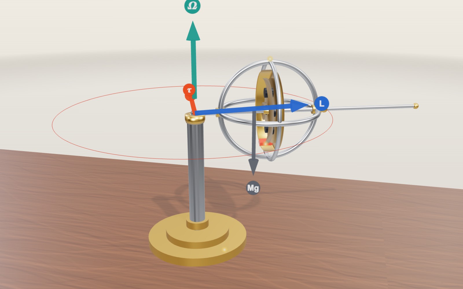
The middle of the workbench holds a brass wheel 110 mm across, set in a steel frame of three rings. A short stem with a ball on the end sticks out of one side of the frame, and the ball sits in a small cup on top of a post. Nothing holds the other end. The wheel turns at 3,000 rpm to begin with, and the whole frame swings around the post about once every 2.8 seconds. That slow sideways swing is called precession.
The readout in the corner shows the spin, the angular momentum L, the torque from the weight, the precession rate the textbook formula predicts and the rate the model actually measures from its own motion. The curve under them is precession rate against spin. The arrows in the scene are the vectors behind the motion: blue for angular momentum, red for torque, grey for weight and green for the precession itself.
On the left of the bench is a wheel held in three gimbals on a fork. You can turn the fork with a slider, and the model also rocks it as a hand would. On the right is an enlarged MEMS gyroscope standing over the small chip it represents, on a turntable you can spin.
Why a spinning wheel turns sideways instead of falling
Start with the wheel not spinning. Its weight, Mg, pulls down at the centre of mass, 80 mm out from the pivot. A force acting at a distance from a pivot is a torque, and this one tries to twist the axle downward about a horizontal line through the pivot. With no spin the result is what you expect. The wheel is a pendulum, and it falls. Set the spin slider to zero and the model does exactly that: the axle drops 52° in about 0.13 seconds and the wheel ends up leaning against the post.
Now give the wheel spin. A spinning wheel has angular momentum, a quantity with a size and a direction. Its size is I·ω, the wheel's moment of inertia about the axle times its rate of spin, and it points along the axle. The rule that connects torque and angular momentum is short:
dL/dt = τ
Torque does not set the direction of the axle. It sets how fast the angular momentum changes, and in which direction. Here the torque is horizontal and at right angles to the axle. So in a short moment the change in L is a small horizontal step sideways, and the tip of the L arrow moves sideways, not down. The axle goes with it. A moment later the axle points a little further around, the torque has turned with it, and the next step is sideways again. The tip of L keeps moving in a circle, and so does the wheel.
This is the part that feels wrong, because a lifetime of dropping things says weight makes things fall. It still does, in a sense. The weight is still changing the angular momentum at a steady rate. When the wheel already holds a large angular momentum along the axle, a steady sideways change turns that angular momentum rather than tipping it over.
The numbers, worked out
The model uses these values (they describe a desk gyroscope of this size, not a particular product):
- total mass M = 0.40 kg, centre of mass d = 0.08 m from the pivot
- moment of inertia about the axle I = 4.5 × 10⁻⁴ kg·m²
- moment of inertia about a horizontal line through the pivot I₁ = 2.81 × 10⁻³ kg·m²
The torque from the weight with the axle level is
τ = M·g·d = 0.40 × 9.81 × 0.08 = 0.314 N·m
At 3,000 rpm the spin is 3,000 × 2π / 60 = 314.2 rad/s, so the angular momentum is
L = I·ω = 4.5 × 10⁻⁴ × 314.2 = 0.141 kg·m²/s
In a time dt the tip of L moves sideways by τ·dt. Divide by the length of L and you get the angle the axle turns through, so the precession rate is
Ω = τ / (I·ω) = 0.314 / 0.141 = 2.22 rad/s
That is 127° per second, and one lap of the post takes 2π / 2.22 = 2.83 seconds. Double the spin to 6,000 rpm and L doubles to 0.283, so Ω halves to 1.11 rad/s and a lap takes 5.66 seconds. At 1,500 rpm it is 4.44 rad/s, a lap every 1.41 seconds. The slower the wheel spins, the faster it precesses. That is why a toy gyroscope speeds up its circling as it runs down, until the circling turns into a wobble and it falls.
The model does not use that formula to move the wheel. It integrates the full equations of motion of a rigid body with a fixed point: dL/dt = τ for the angular momentum, and da/dt = ω × a for the direction a of the axle, with the angular velocity ω worked out from L and the two moments of inertia. The integration uses fourth-order Runge-Kutta in steps of half a millisecond. Then it measures how fast the axle actually goes around. Started at 2,000 rpm with the matching sideways speed, the integrated precession is 3.331 rad/s. At 4,000 rpm it is 1.665 rad/s. The ratio is 2.000, which is the inverse proportion the formula promises. For an axle that is exactly level the formula is exact and needs no fast-spin approximation, and the integrator agrees with it to the third decimal place.
Nutation: the nod you get when you let go
Precession at a steady rate needs the wheel to be moving sideways at the right speed already. The formula above describes that steady state. If you hold the frame still and simply let go, the wheel starts with no sideways motion at all, and gravity has to provide it. For a moment the axle does start to fall. As it falls, the torque builds up sideways motion, which in turn lifts the axle back up. The axle overshoots, stops, dips again and keeps nodding while it precesses. This nodding is called nutation.
Switch on "Release from rest" and the model lets go of the wheel this way. The red line traces the end of the axle. Instead of a smooth circle it draws a row of loops with sharp cusps at the top, the points where the axle stops for an instant before dropping again.
For a fast wheel there are two handy estimates. The axle dips by about 2·I₁·τ / L² radians and nods about L / (2π·I₁) times a second. At 3,000 rpm they give a 5.1° dip and 8.0 nods per second; the integrated motion gives 5.0° and 8.05. At 1,500 rpm the wheel is no longer "fast" in this sense, and the estimates drift: 20° and 4.0 per second predicted, 18.5° and 4.3 per second from the integration. Spin the wheel at 6,000 rpm and the dip shrinks to 1.3°, a shiver you would hardly notice. Because the dip grows with 1/L², a well-spun gyroscope barely nods at all.
Released from rest, the wheel's average precession is a little slower than the steady rate, 4.20 rad/s instead of 4.44 at 1,500 rpm. Below a few hundred rpm the dip is so large that the wheel hits the post before it can recover. In a real gyroscope friction at the pivot damps the nodding within seconds and leaves the smooth precession. The model has no friction, so it keeps nodding until you change something.
A wheel in three gimbals keeps its direction
A gimbal is a ring that can turn on two pins. Put one ring inside another, with each pair of pins at right angles to the last, and the innermost ring can take up any orientation without its bearings twisting it. The left-hand exhibit has three of them. The outer gimbal turns on vertical pins in the fork, the middle one on horizontal pins in the outer ring, and the inner one on pins in the middle ring. The inner ring carries the spinning wheel.
Turn the "Turn the gimbal mount" slider and the fork swings around, while the model rocks it on its ball joint as well. The rings move to take up the motion and the wheel's axle keeps pointing in the same direction, along the faint blue line. The reason is the same rule as before. With perfect pivots no torque can reach the wheel, and with no torque dL/dt = 0, so L, and the axle with it, stays fixed in space.
Strictly, even a wheel that is not spinning would stay put if the bearings were perfect, because nothing would turn it. Spin matters because real bearings are not perfect. A small friction torque τ_f makes a spinning wheel drift at only τ_f / L, and a fast heavy rotor has a large L. That is what made gyroscopes useful for navigation: an axle that holds its direction while the ship, aircraft or rocket turns around it. In this part of the exhibit the model solves for the ring angles that keep the wheel's orientation fixed; it does not integrate the dynamics of the rings.
How the gyro in a phone works
A phone has no spinning wheel. Its gyroscope is a MEMS device, a microelectromechanical system: a few millimetres of silicon with parts etched into it that can move by microns. Instead of something spinning, a small proof mass is driven back and forth along one direction at a steady resonant frequency, typically tens of kilohertz. The chip measures how fast it is being turned, not which way it points.
The physics behind it is the Coriolis force. Seen from a turning frame, a mass moving with velocity v is pushed sideways by a force −2m(Ω × v), at right angles to its motion. If the chip is not turning, the proof mass moves straight back and forth. If the chip turns at a rate Ω about the axis at right angles to the chip, the mass is pushed to one side while it moves one way and to the other side on the way back. The mass hangs in a frame on springs that let it move only across the drive direction. The frame carries rows of fingers interleaved with fixed fingers, and these form capacitors. When the frame shifts, the gaps change and so does the capacitance, which the circuit turns into a rate.
Turn the "Turn the MEMS gyro" slider and the turntable carries the chip and the enlarged model around. The blue arrow is the drive velocity and the red one is the Coriolis force, swinging from side to side in step with it. The second readout gives the numbers for a typical case (an illustration, not a datasheet). With a drive amplitude of 10 µm at 20 kHz the mass reaches 1.26 m/s. At 100° per second, about the rate at which you turn a phone to look at it, the Coriolis acceleration is 2 × 1.745 × 1.26 = 4.4 m/s², nearly half of g. If the sense springs are tuned to 22 kHz, that moves the frame by about 1.3 nanometres. The movements in the model are magnified millions of times.
The structure shown here is simplified from published descriptions, such as Analog Devices' account of its resonating-mass gyros. Many real chips use two or four masses moving in opposite directions, so that ordinary acceleration and vibration cancel while the rotation signal adds up. Phones carry three-axis gyros, which sense turning about all three axes.
A spinning wheel and a vibrating mass compared
| Spinning-wheel gyroscope | MEMS gyroscope | |
|---|---|---|
| Moving part | Rotor spinning at thousands of rpm | Silicon mass vibrating at tens of kHz |
| What it gives | A direction that holds still | A rate of turning |
| Physics used | Angular momentum, dL/dt = τ | Coriolis force, −2m(Ω × v) |
| Size | Hand-sized to ship-sized | A few millimetres |
| Main weakness | Bearing friction, wear, spin-up time | Small errors in the rate add up |
The last row matters for phones. To know which way the phone faces, its software adds up the rate over time. An error of just 0.01° per second becomes 0.6° after a minute and 36° after an hour. That is why phones combine the gyro with the accelerometer, which knows where down is, and the magnetometer, which knows roughly where north is.
What this model leaves out
- No friction. In the model the wheel keeps its spin at the slider value forever and nutation never dies away. A real toy gyroscope slows down, precesses faster and faster, wobbles and falls within a minute or two.
- The wheel and frame are treated as one rigid body symmetric about the axle, with the moments of inertia listed above. The rings of the frame are not given their own mass.
- When you change the spin, the model changes it instantly, as if a motor inside the frame had done it. With "Release from rest" off, it also gives the wheel exactly the sideways speed for steady precession.
- When the spin is zero or too low, the wheel stops where its rim would meet the post, 52° below level, and the model later lifts it back by hand.
- The gimbal wheel's orientation is held fixed by solving for the ring angles. The MEMS motion is the steady response of a driven spring and mass, drawn with huge magnification and slowed from 20 kHz to about one cycle a second.
Where the gyroscope came from
Spinning tops are ancient, but the instrument has a recorded starting point. In 1817 Johann Bohnenberger, a professor at Tübingen, described a heavy spinning sphere held in gimbals, which he called simply "the Machine". It was used in lectures to show how a spinning body keeps its axis and to illustrate the precession of the Earth's own axis. In 1832 the American Walter R. Johnson built a similar device with a disc instead of a sphere.
In February 1851 Léon Foucault showed the Earth's rotation with his pendulum in Paris. In 1852 he followed it with a carefully made spinning rotor in gimbals, meant to show the rotation more directly, and in the paper describing it he proposed the name gyroscope, from the Greek words for rotation and for looking. His rotor could be kept spinning for only about 8 to 10 minutes before friction slowed it, long enough to see the slow apparent turning that the Earth's rotation causes.
Electric motors later made it possible to keep a rotor spinning indefinitely. In Germany Hermann Anschütz-Kaempfe built a working gyrocompass that passed its tests in 1908 and went into use in the German navy, and Elmer Sperry's gyrocompass was adopted by the U.S. Navy in 1911. In 2003 Analog Devices described its ADXRS150 and ADXRS300 as the first commercially available surface-micromachined rate gyros with integrated electronics, and MEMS gyros are now standard in phones.
A bicycle wheel calculation and its limits
The equation Ω = mgr/(Iω) uses r for the distance from the support to the centre of mass; this is the same distance called d above. It is not the radius of the spinning wheel. Confusing those distances can give a plausible-looking answer for the wrong apparatus. The mass m is the total supported mass, while I describes the rotating mass about its spin axis. A heavy axle contributes to the gravitational torque without necessarily contributing much spin angular momentum.
Consider an assumed classroom bicycle-wheel demonstration, not a measurement of the wheel on this screen. Let m = 2 kg, r = 0.10 m and I = 0.12 kg·m². At 600 rpm, ω = 600 × 2π/60 = 62.83 rad/s. The weight supplies 1.962 N·m of torque and the rotor holds 7.54 kg·m²/s of angular momentum. The predicted steady precession is 0.260 rad/s, giving a circuit in about 24.2 s. Doubling the spin to 1,200 rpm gives 0.130 rad/s and a 48.3 s circuit. These calculations assume a horizontal axle and steady precession, with negligible bearing losses.
For a top the support lies beneath the centre of mass rather than at the end of a horizontal axle. Both the gravitational torque and the horizontal radius traced by the angular-momentum vector contain a sine of the tilt angle. Those factors cancel in the usual fast-top approximation. That cancellation does not mean every slow top obeys the same simple formula: transverse angular momentum becomes important, and a general steady tilted top has additional terms. At zero spin the division by ω is undefined. It predicts neither infinitely fast circling nor a substitute for the full falling motion.
Hubble measures rotation and changes it with different hardware
A telescope in orbit has no floor to brace against. To turn the observatory, a motor accelerates a reaction wheel inside it. Angular momentum gained by the wheel is balanced by an opposite change in the spacecraft, apart from external torques. Holding a wheel at an unchanging speed does not continually turn the telescope faster. It is the change in wheel momentum that supplies the control torque. This distinction separates a reaction wheel, an actuator, from a gyro used as a sensor.
NASA describes Hubble's pointing system as a combination of sensors and actuators. Its mechanical rate gyros measure the direction and rate of turning; their rotors spin at 19,200 rpm. The reaction-wheel assemblies physically change the telescope's attitude. Star trackers and fine guidance sensors provide information that a rate sensor cannot supply by itself. The computer combines those measurements rather than treating a freely spinning axis as a complete celestial map.
In its June 2024 announcement NASA explained the planned transition to one-gyro operation, using other sensors alongside the remaining gyro. This was a way of extending useful operations, not proof that one sensor suddenly measured every rotation component independently. Acquiring a target takes longer and some observing flexibility is lost. The announcement describes a dated operational decision, not a count of healthy gyros today.
Reaction wheels also have a practical limit: persistent external torques can build up wheel speed. Hubble uses magnetic torquers interacting with Earth's magnetic field to manage that momentum. Conservation applies to the complete system, including the external interaction. An internal motor alone cannot erase the total angular momentum of an isolated spacecraft. The gimballed wheel on this page demonstrates direction holding, but it does not simulate Hubble's feedback controller or its momentum unloading.
Light can measure rotation without a spinning rotor
An optical gyro sends light around a closed path in opposite directions. Rotation produces a difference between the travel times, called the Sagnac effect. For a simple loop in vacuum at ordinary rotational speeds, Δt ≈ 4AΩ/c², where A is the enclosed area projected perpendicular to the rotation axis and c is the speed of light. This is a comparison between counter-propagating paths in a rotating apparatus. It does not require light to travel faster in one direction according to a local observer.
A ring laser makes the two directions into oscillations of a laser cavity. Rotation produces a frequency difference, read as a beat signal. A fibre-optic gyro usually splits an external light source into beams that travel both ways through a coil, then measures their relative phase. Winding many turns increases the accumulated response without requiring a room-sized loop. These devices sense rotation rate; their output still needs integration, calibration and an external reference when long-term absolute orientation is required.
Optical does not mean error-free. Backscattered light can couple the counter-propagating modes of a ring laser and cause lock-in near zero rotation. Mechanical dithering is one established response, so saying that every laser gyro has no moving parts is too broad. Fibre systems have their own temperature and nonreciprocity errors. The cited reviews distinguish these engineering problems from the underlying Sagnac signal. Neither optical design is represented by the vibrating silicon structure on the right of this exhibit.
Why a moving bicycle stays upright
A spinning front wheel can couple leaning to steering, but its angular momentum is not a complete explanation of bicycle balance. In 2011 Kooijman and colleagues reported a bicycle that could balance itself without the usual gyroscopic effect or positive trail. Counter-rotating discs cancelled the wheel angular momenta, and the steering geometry gave slightly negative trail. When pushed sufficiently fast, the experimental machine could still recover from a small sideways disturbance.
The result does not establish that gyroscopic torque is always negligible on every bicycle. It establishes that it is not necessary for self-stability. Mass distribution and the way leaning produces steering also matter. A rider adds active control, moving the steering and body so the contact points return beneath the combined centre of mass. Holding a spinning wheel in your hands demonstrates a real torque, but it does not isolate all the mechanisms of a rolling bicycle. A bicycle constrained so that its steering cannot respond is a different experiment again.
Checks to make on the screen
Use the spin control to compare 3,000 rpm with 6,000 rpm while “Release from rest” is off. Watch the measured precession as well as the predicted value. The expected change is from about 2.22 rad/s to 1.11 rad/s, with the circuit time increasing rather than decreasing. This compares two steady initial conditions; it is not a recording of a real motor accelerating the same wheel.
Next enable “Release from rest” at 3,000 rpm. The trace should show the nodding that was absent from the steady start. Increasing spin reduces the dip because its fast-spin estimate depends on the inverse square of angular momentum. Do not read an individual loop as a second rotor rotation: the trace follows the axle end, not a painted mark on the spinning rim.
Finally change “Turn the MEMS gyro” through zero and into the opposite direction. The drive vibration remains, while the rotation-dependent sideways response reverses. Turning a mount is not the same operation as increasing a rotor's spin. The enlarged motion makes phase and direction visible, not the true size of a silicon displacement. In a real phone, integrating a biased rate still drifts even when the displayed vibration looks perfectly regular.
Swipe across the rim of the wheel, or press Flick the wheel, and the spin rises by up to 1,500 rpm at a time. Grab the end of the axle and push it down: instead of dropping, the axle swings sideways faster, and the purple F arrow and the red τ arrow show why. Push it sideways along its circle and the axle climbs; push it against the circle and it dips. Hang a weight on the end of the axle and lengthen the arm: the torque grows by m·g·r and the precession Ω = τ / (I·ω) speeds up in step.
Turn on Friction to watch the wheel run down. The friction values are model values: the spin decays with a time constant of 14 seconds and the pivot resists the circling. As the spin falls the precession speeds up and the axle droops until the wheel leans on the post. In the MEMS scene, drag the turntable round or, on a phone, press Use my phone’s gyro: the turn rate your phone measures then drives the turntable and the Coriolis readout.
Questions
Why doesn't a gyroscope fall?
Its weight still makes a torque, but torque changes angular momentum rather than setting the axle's direction. With a large angular momentum along the axle, a sideways torque turns the axle sideways, so the gyroscope precesses around the pivot instead of dropping. Remove the spin and it falls in about 0.1 seconds.
What is precession?
Precession is the slow turning of a spinning object's axis caused by a torque. For a gyroscope resting on a pivot with its axle level, the rate is Ω = τ / (I·ω): the torque from the weight divided by the angular momentum.
Why does a gyroscope precess faster as it slows down?
The precession rate is the torque divided by the angular momentum. The torque stays the same, while the angular momentum falls as the spin falls, so the rate rises. Halve the spin and the precession doubles.
What is nutation?
Nutation is a nodding of the axle on top of the precession. It appears when the gyroscope is released without the sideways speed that steady precession needs. The faster the spin, the smaller and quicker the nod.
Which way does a gyroscope precess?
The axle moves in the direction of the torque. Point the fingers of your right hand around the spin and your thumb gives the direction of L. The torque from the weight is horizontal and at right angles to the axle, and the tip of L moves that way. Reverse the spin and the precession reverses.
Does a phone gyroscope spin?
No. A phone uses a MEMS gyroscope, in which a tiny silicon mass vibrates back and forth. When the phone turns, the Coriolis force pushes the mass sideways by a few nanometres, and capacitors measure the shift.
What is the difference between a gyroscope and an accelerometer?
An accelerometer measures acceleration in a straight line, including gravity, so it can tell which way is down. A gyroscope measures how fast the device turns. Phones use both, and add a magnetometer, because each one covers the other's errors.
Are Hubble's gyroscopes the wheels that turn it?
No. Rate gyros measure rotation; reaction wheels change the spacecraft's angular momentum distribution to turn it. Other sensors provide pointing references, and magnetic torquers help manage accumulated momentum.
Must a bicycle have gyroscopic wheel momentum to balance itself?
No. Kooijman and colleagues demonstrated self-stability with the wheel gyroscopic effects cancelled in 2011. Gyroscopic coupling can still contribute on ordinary bicycles; the experiment disproves necessity, not every possible contribution.
Does an optical gyro contain a spinning wheel?
No rotor is required for the sensing principle. Ring laser and fibre-optic gyros use the Sagnac effect in opposite light paths. Some ring laser instruments mechanically dither to avoid lock-in, so the whole instrument need not be motionless.
Why does a MEMS gyro still drift when the phone is stationary?
A small bias can remain in its measured rate even at rest. Integrating that false rate accumulates an orientation error. Calibration and other sensors reduce it; vibration alone does not establish an absolute direction.
Terms
- Angular momentum (L): The spinning counterpart of momentum. For a wheel, L = I·ω, pointing along the axle.
- Moment of inertia (I): How hard a body is to spin up about an axis. Mass far from the axis counts most.
- Torque (τ): A turning effect of a force, τ = r × F. It changes angular momentum at the rate dL/dt = τ.
- Precession: The slow turning of a spinning body's axis under a torque.
- Nutation: A nodding of the axis that rides on top of the precession.
- Gimbal: A ring on two pins. Nested gimbals let the inner part take any orientation.
- Coriolis force: The sideways push a moving mass feels in a turning frame, −2m(Ω × v).
- Proof mass: The small moving mass in a MEMS sensor whose displacement is measured.
- MEMS: Microelectromechanical systems, machines etched into silicon.
Sources
Philip K. Allan, A History of the Ship's Compass, Naval History 36(6), U.S. Naval Institute, December 2022 (page answers scripted requests with 403; Anschütz-Kaempfe's gyrocompass adopted by the Imperial German Navy two years after 1906; Sperry's adopted by the U.S. Navy in 1911). https://www.usni.org/magazines/naval-history-magazine/2022/december/history-ships-compass (checked 17 October 2026)
The Franklin Institute, Case Files: Elmer A. Sperry (Gyroscopic Compass) (page answers scripted requests with 403; Anschütz-Kaempfe's gyrocompass passed its tests in 1908; Sperry's work from 1911). https://fi.edu/en/science-and-education/collection/case-files/elmer-sperry-gyroscopic-compass (checked 17 October 2026)
Institute of Navigation Museum, The Machine of Bohnenberger. https://www.ion.org/museum/Machine-of-Bohnenberger.cfm (checked 16 October 2026)
Kenyon College, Early Apparatus, Bohnenberger's Apparatus. https://physics.kenyon.edu/EarlyApparatus/Mechanics/Bohnenbergers_Apparatus/Bohnenbergers_Apparatus.html (checked 16 October 2026)
American Physical Society, April Meeting 2012, On the Late Invention of the Gyroscope. https://meetings-archive.aps.org/apr/2012/j15/1 (checked 16 October 2026)
J. Sommeria, Foucault and the rotation of the Earth, Comptes Rendus Physique 18 (2017). https://comptes-rendus.academie-sciences.fr/physique/articles/10.1016/j.crhy.2017.11.003/ (checked 16 October 2026)
Georgia State University HyperPhysics, Precession of Spinning Top. http://hyperphysics.phy-astr.gsu.edu/hbase/top.html (checked 16 October 2026)
Georgia State University HyperPhysics, Gyroscope. http://hyperphysics.phy-astr.gsu.edu/hbase/gyr.html (checked 16 October 2026)
J. Geen and D. Krakauer, New iMEMS Angular-Rate-Sensing Gyroscope, Analog Dialogue 37-03 (2003), copy at Carnegie Mellon University. https://www.cs.cmu.edu/~sensing-sensors/readings/vibrational_gyro-coriolis.pdf (checked 16 October 2026)
A Review of MEMS Vibrating Gyroscopes and Their Reliability Issues in Harsh Environments, Sensors (2022), PubMed Central. https://pmc.ncbi.nlm.nih.gov/articles/PMC9571586 (checked 16 October 2026)
Calculations on this page: τ = M·g·d, L = I·ω, Ω = τ / L with M = 0.40 kg, d = 0.08 m, I = 4.5 × 10⁻⁴ kg·m², I₁ = 2.81 × 10⁻³ kg·m² (model values).
NASA, Hubble Pointing Control System (rate gyros, reaction wheels and magnetic torquers). https://science.nasa.gov/mission/hubble/observatory/design/pointing-control/
NASA, NASA to Change How It Points Hubble Space Telescope (June 2024 decision). https://science.nasa.gov/missions/hubble/nasa-to-change-how-it-points-hubble-space-telescope/
Cornell University, Researchers explain why bicycles balance themselves (Kooijman et al., Science, 2011). https://news.cornell.edu/stories/2011/04/researchers-explain-why-bicycles-balance-themselves
Choi et al., Sagnac Effect Compensations and Locked States in a Ring Laser Gyroscope, Sensors (2023). https://pmc.ncbi.nlm.nih.gov/articles/PMC9920103/
Rotation Active Sensors Based on Ultrafast Fibre Lasers, Sensors (2021). https://pmc.ncbi.nlm.nih.gov/articles/PMC8159120/
More exhibits
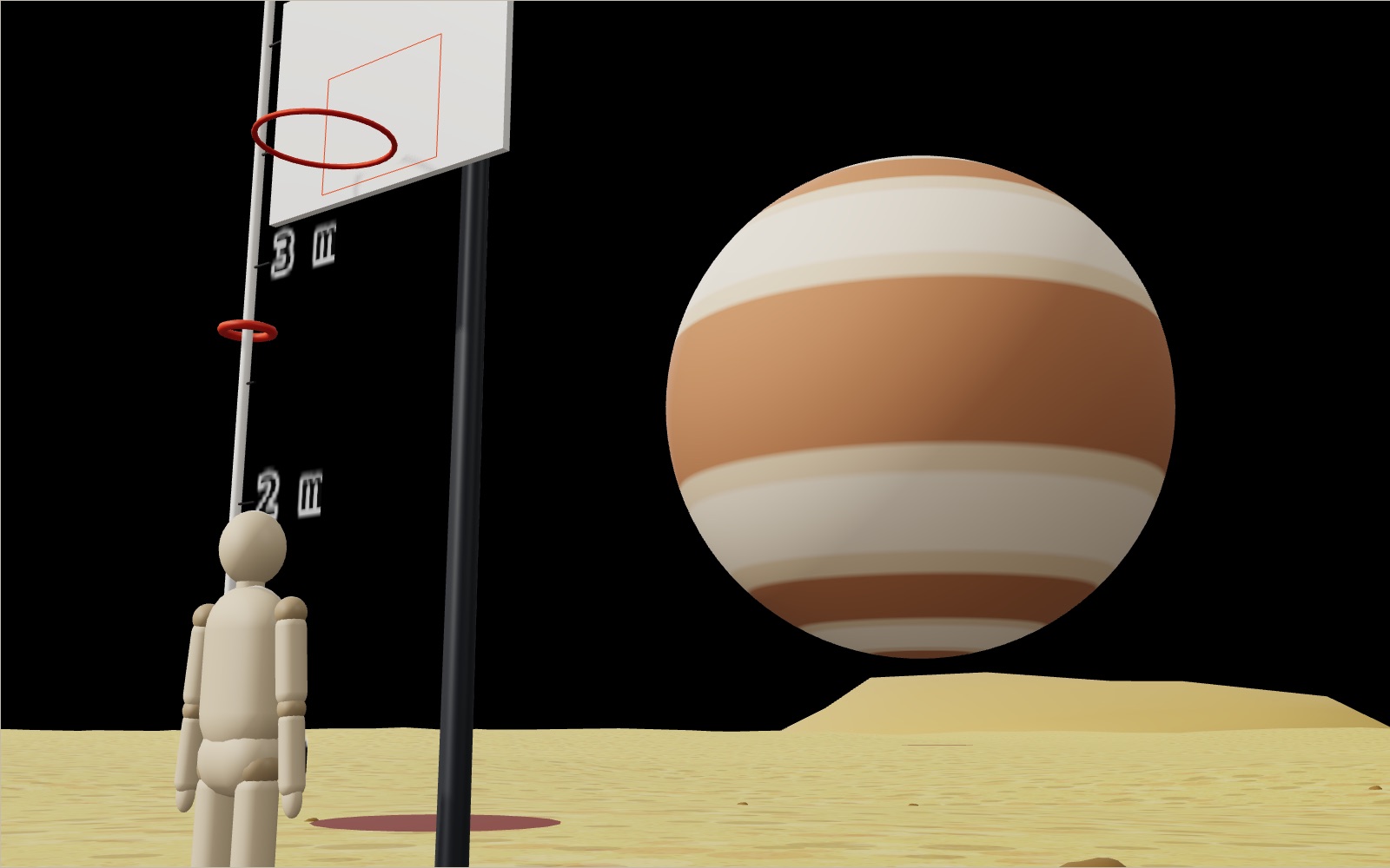
Your weight and jump height on other planets and moons
A 50 cm jump on Earth becomes a 3 m leap on the Moon, 18 m on Ceres and a one-way trip off asteroid Bennu.
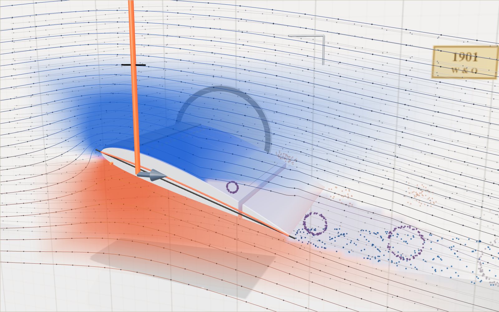
How a wing makes lift, and what changes as the angle grows
Air over the top of a wing reaches the trailing edge first. It does not wait for the air underneath.
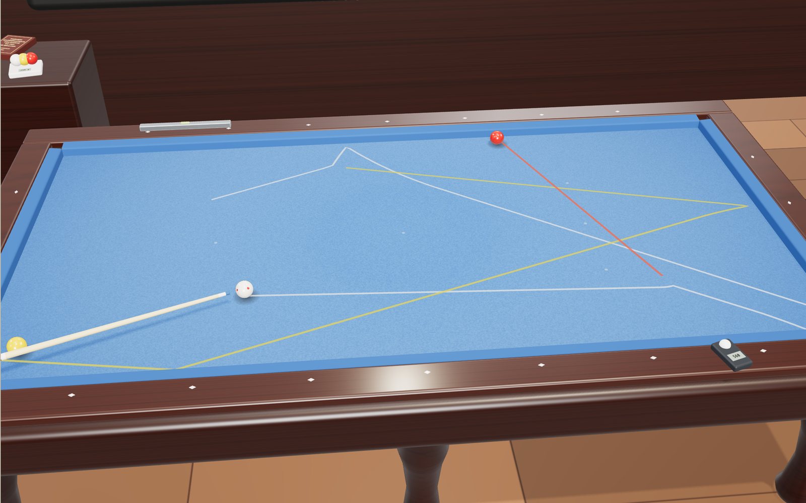
Billiards angles: aiming, spin and the diamond system, step by step
Two equal balls that meet without spin part at a right angle, and a ball struck at its centre slides for 12/49 of v²/μg before it starts to roll.
Pulley and hydraulic jack simulator: lift a crate and a car
A 50 kg crate can be lifted with an 82 N pull, as long as you are willing to pull six metres of rope for every metre it rises.
Roller coaster physics: how roller coasters work
A train that creeps over a 42 m lift hill at 3 m/s is doing 99 km/h at the bottom, and nothing but gravity has pushed it.
How does an elevator work? Counterweight and safety brake
A lift car full of people can weigh almost two tonnes, yet the motor that raises it only has to lift about a quarter of that, because a counterweight hangs on the other end of the ropes.
Travelling at the speed of light
Light goes round the equator 7.5 times in a second, yet the same light needs 2.5 million years to reach the Andromeda galaxy.

Satellites orbiting Earth right now
On 20 October 2026 the public catalogue listed 16,768 working satellites, and two in every three belonged to one company's internet network.
How does a vending machine recognise coins?
A 100 won coin is not attracted to a magnet, yet the magnet inside a vending machine is what tells it from a copper fake.
How to tie knots: 40 knots step by step
In one set of break tests a bowline kept about 63% of the rope's strength and a sheet bend about half.

What happens to your body in space without a suit
Without a suit you would have about 10 seconds of useful consciousness, and if air came back within a minute or so you might well recover. You would not explode.

Northern lights over an Arctic village
The green of the northern lights comes from oxygen about 100 km up, and in the biggest storms the red glow above it can be seen as far south as Korea.