FIG. 05How It Works
How does a differential work in a car? A 3D gear model
Round a 10 m bend at 50 km/h and the outer rear wheel turns 17% faster than the inner one, yet both are driven from the same shaft.
This device cannot show the 3D model. You can read the guide steps below as text.
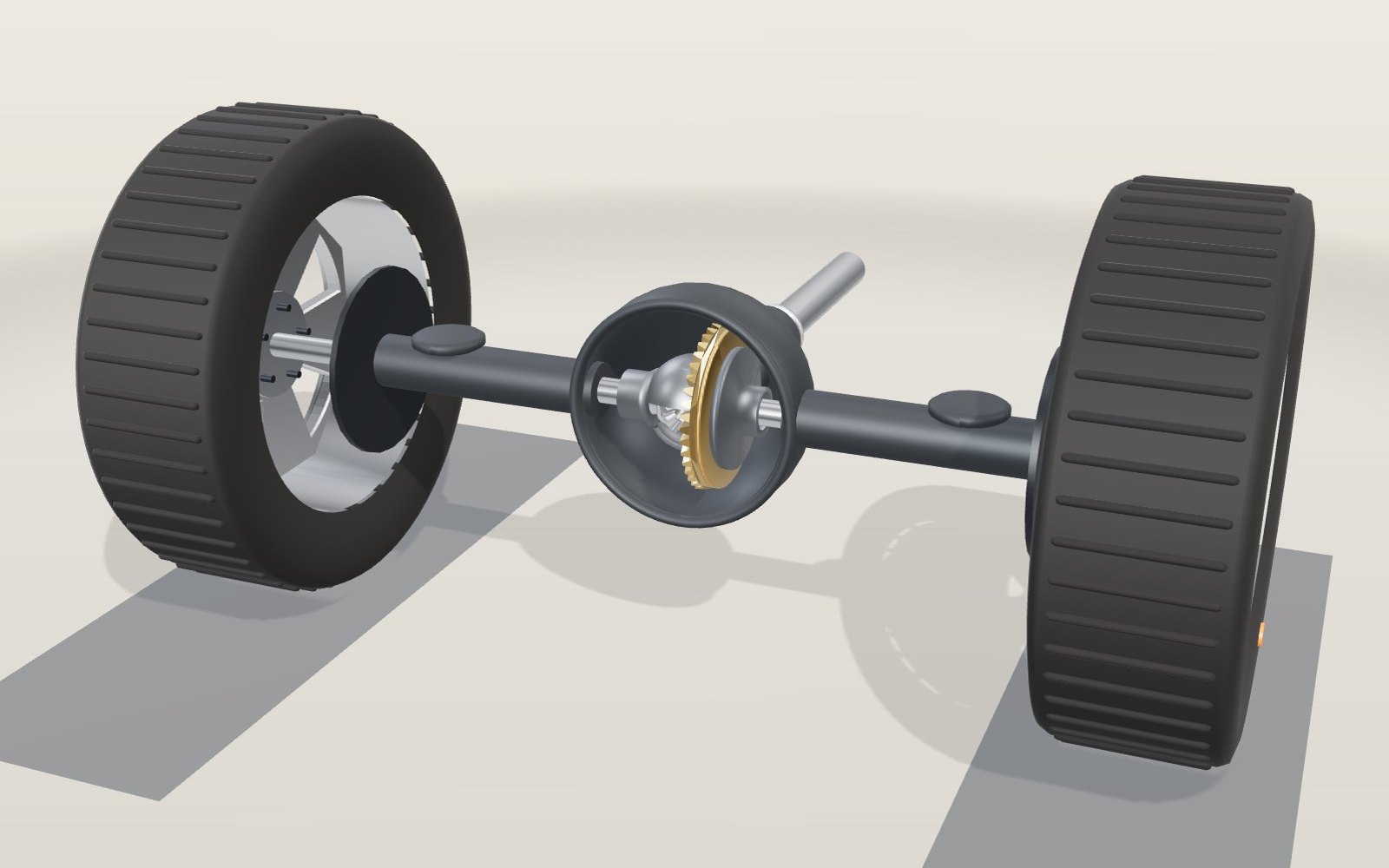
1 / 8 A rear axle with the cover offThe propeller shaft brings the engine's turning from the front of the car. The gears in the middle split it between the left and right wheels. Drag to look around.
Drag to turn. Scroll or pinch to zoom.
What the model shows
How does a differential work in a car? It lets the two driven wheels turn at different speeds while sharing power, so the outer wheel can travel farther through a corner. Drive round a tight corner and the two rear wheels cover different distances. The outer wheel follows a bigger circle, so it has to turn faster than the inner one. Both wheels still get their power from one engine through one propeller shaft. The gearbox that lets that happen sits in the bulge in the middle of a rear axle, and it is called the differential.
The model is a rear axle with the back cover taken off. Power comes in along the propeller shaft from the front of the car, turns a corner through a pinion and a ring gear, and is then shared between the two half shafts by four small bevel gears inside a rotating case. "See inside" makes the axle housing and the case transparent, "Take apart" pulls all ten parts away from each other, and the "Turn radius" slider steers the car left or right. The panel in the corner shows the real speeds that go with each setting for a car driving at 50 km/h.
Why one solid axle would not work
Suppose the two rear wheels were fixed to a single solid shaft. They would always turn at the same speed. In a straight line that is fine. In a turn, one of the tyres would have to scrub sideways across the road the whole way round, because the outer wheel needs to travel further than the inner one in the same time. Go-karts and trams use solid axles and accept that wheel slip, but a road car would wear its tyres and fight its own steering.
How much further does the outer wheel go? Take a car with a rear track (the distance between the centres of the two rear tyres) of 1,564 mm. That is the rear track of a Hyundai Elantra Active on 205/55 R16 tyres, from Hyundai Australia's specification sheet. If the middle of the rear axle follows a circle of radius R, the inner wheel follows a circle of R − 0.782 m and the outer wheel R + 0.782 m. On a 10 m turn that is 9.218 m against 10.782 m, so the outer wheel travels 17% further.
There is a neat result hiding here. For one full circle, the outer wheel travels 2π(R + T/2) and the inner wheel 2π(R − T/2). The difference is 2πT, which does not depend on R at all. With T = 1.564 m the outer wheel always covers 9.83 m more per full circle, whether the circle is 10 m or 100 m across. A 205/55 R16 tyre has a nominal diameter of 16 × 25.4 + 2 × 0.55 × 205 = 631.9 mm, so a circumference of 1.985 m, and 9.83 m is 4.95 extra turns of the outer wheel.
How the power reaches the wheels
Follow the drive from the front of the car to the road.
- Propeller shaft. It comes from the gearbox and turns the drive pinion.
- Drive pinion. In the model it has 11 teeth and meshes with the ring gear at a right angle, which turns the drive from along the car to across it.
- Ring gear. It has 41 teeth, so the pinion turns 41 ÷ 11 = 3.73 times for each turn of the ring gear. This final reduction is often called the axle ratio.
- Differential case. The ring gear is bolted to it, so the two always turn together. A steel cross pin passes through the case.
- Spider gears. Two 10-tooth bevel gears sit on the cross pin. They are free to turn on it.
- Side gears. Two 16-tooth bevel gears, one on each side, mesh with both spider gears. Each one is splined to a half shaft.
- Half shafts and wheels. Each half shaft carries the drive out to one wheel.
The engine never drives the side gears directly. It drives the case, and the case pushes the side gears round through the spider gears. That indirect path is what gives the wheels their freedom.
Why the spider gears stand still on a straight road
On a straight road both wheels turn at the same speed, and so do both side gears. The spider gears are pushed round by the cross pin, and their teeth are locked between two side gears moving at the same speed. They have no reason to turn on the pin. The whole assembly goes round like one solid block. In the model, the orange dot on each spider gear travels round with the case but stays in the same place on the gear.
Now steer left. The left wheel has a shorter path and the road slows it down. The right wheel has a longer path and has to speed up. The side gears now turn at different speeds, and the spider gears between them have to roll: they turn on the cross pin while still being carried round by the case. Turn the slider and the orange dots start to spin.
The average rule
Look at the gears from inside the case, as if you were riding on it. From there the case stands still, the left side gear turns at ω_L − ω_case and the right side gear at ω_R − ω_case. Both side gears mesh with the same spider gear at the same distance from its pin, so the spider gear forces them to move by equal amounts in opposite directions:
ω_L − ω_case = −(ω_R − ω_case)
Rearranged, that gives the rule that the panel in the model checks for every setting:
ω_case = (ω_L + ω_R) / 2
The case always turns at the average of the two wheel speeds. If one wheel speeds up, the other has to slow down by the same amount, unless the case itself changes speed. The spider gears spin at (Z_side ÷ Z_spider) × (ω_R − ω_L) ÷ 2, which is 1.6 times half the difference with 16-tooth side gears and 10-tooth spiders.
Wheel speeds in numbers
At 50 km/h, or 13.889 m/s, a tyre with a radius of 0.316 m turns at 13.889 ÷ 0.316 = 43.96 rad/s, which is 419.8 rpm. The propeller shaft turns 3.73 times faster, at 1,565 rpm. In a turn, each wheel's speed scales with the radius of its own path: ω_inner = ω × (R − T/2) ÷ R and ω_outer = ω × (R + T/2) ÷ R, where R is the radius followed by the middle of the rear axle.
| Turn radius R | Inner wheel | Outer wheel | Average (case) | Spider gear spin |
|---|---|---|---|---|
| Straight | 419.8 rpm | 419.8 rpm | 419.8 rpm | 0 rpm |
| 100 m | 416.5 rpm | 423.1 rpm | 419.8 rpm | 5.3 rpm |
| 25 m | 406.6 rpm | 432.9 rpm | 419.8 rpm | 21.0 rpm |
| 10 m | 387.0 rpm | 452.6 rpm | 419.8 rpm | 52.5 rpm |
| 5 m | 354.1 rpm | 485.4 rpm | 419.8 rpm | 105.0 rpm |
The case speed stays the same in every row, because the car's speed (measured at the middle of the axle) stays the same. Only the split between the wheels changes. In the model the gears run at a fraction of these speeds so you can follow the teeth, which is what the "Slow motion" setting changes.
One wheel on ice
The same freedom that helps in a turn causes trouble on a slippery road. The spider gears behave like a balance beam: as long as they turn freely, they push equally hard on both side gears. An ideal open differential in steady operation therefore sends the same torque to the left and right wheels.
That is fine when both tyres grip. It is a problem when one of them is on ice. The tyre on ice can only resist a small torque before it slips, and the differential gives the other wheel the same small torque. The car does not move. The ice wheel spins, the dry wheel stands still, and the average rule still holds: with ω_R = 0, ω_L = 2 × ω_case. Switch on "Left wheel on ice" and the left wheel turns at 839.6 rpm while the right one stops. That is the speed of a tyre surface moving at 100 km/h, going nowhere.
A slope makes the problem easy to put into numbers. The specification sheet gives the lightest Elantra a kerb weight of 1,260 kg. On a 5% grade, holding the car against gravity takes a force of 1,260 × 9.80665 × sin(arctan 0.05) = 617 N. At a tyre radius of 0.316 m that is 195 N·m at the wheels, or 97 N·m per wheel if the two share it equally. If the tyre on ice slips at less than 97 N·m, an open differential cannot climb the hill, however much torque the engine has. (The Elantra drives its front wheels. We only borrow its measurements.)
Limited-slip differentials were made for this. They let the wheels turn at different speeds but resist large differences, so more torque can go to the wheel with grip. Clutch packs, cones and worm-gear designs such as the Torsen all do this in different ways. Locking differentials go further and join both wheels together on demand, which off-road vehicles use. The model shows only the open type.
Where the model is simpler than a real axle
- The gear teeth are straight bevels. Most rear-drive cars use a hypoid ring and pinion: curved teeth, with the pinion set below the centre line of the ring gear. The offset lets the propeller shaft sit lower, which shrinks the tunnel in the floor, and lets more teeth share the load. The cost is sliding between the teeth, which needs special extreme-pressure gear oil and wastes a little energy. In the model the pinion axis passes straight through the centre of the ring gear, so the cone geometry is easy to see.
- The tooth counts are our choice. 11 and 41, 10 and 16 were picked to give clear ratios. A real axle's numbers depend on the car.
- The half shafts are shortened. On the real car the wheel centres are 1,564 mm apart.
- The tyre radius is the nominal one. A loaded tyre squashes a little, so its rolling radius is slightly smaller and it turns slightly faster than the table shows.
- The turn is ideal. The calculation assumes the turning centre lies on the line of the rear axle and that the tyres do not slip. Real tyres always run at a small slip angle.
- Bearings, thrust washers and oil are left out.
A short history
In the 1820s the French clockmaker Onésiphore Pecqueur designed a steam car, and his French patent described a gear box that let the two sides of the driven rear axle turn at different speeds. The car was never built, but the same idea sits in the driven axle of cars today. The hypoid gears that most rear axles now use came later: NASA's gearing handbook dates their first practical use to a Packard car in 1926 and notes that by 1937 almost all cars had hypoid rear axles.
Limited-slip designs came later; Vernon Gleasman, for example, was granted a US patent for a geared differential mechanism in 1958. A short 1937 film called Around the Corner, made by the Jam Handy Organization to explain how a differential lets a car turn, can still be watched at the Internet Archive.
A calculation from road speed to shaft speed
The radius in the turn calculation belongs to the path of the axle midpoint, not to the tyre. These two radii have different jobs. The path radius determines how the distance is divided between the wheels; the tyre radius converts distance along the ground into wheel rotation. Confusing them gives an answer with the wrong physical meaning even when the arithmetic is tidy.
Take the existing 10 m example and keep the model's 50 km/h speed at the axle midpoint. This is an ideal geometric example, not advice to take such a tight bend at that speed. The car's angular speed about the turning centre is 13.889 ÷ 10 = 1.3889 rad/s. Multiply that by each wheel's path radius: the inner wheel travels at 1.3889 × 9.218 = 12.803 m/s, and the outer one at 1.3889 × 10.782 = 14.975 m/s. Dividing each by the tyre radius of 0.316 m gives its angular speed about its own axle. Multiplying by 60 ÷ (2π) converts radians per second to revolutions per minute. The results are approximately 387.0 and 452.6 rpm.
Their mean is still 419.8 rpm. The ring gear and case therefore keep the straight-road speed while the side gears change their relative motion. The propeller shaft must turn at the case speed multiplied by 41 ÷ 11, approximately 1,565 rpm. Do not multiply just the outer wheel speed by the axle ratio: the ring gear is attached to the case, not to either individual wheel. The final reduction and the differential action happen in the same housing, but they describe different relationships.
Another useful check is to halve the assumed road speed while keeping the same turn geometry. Both wheel speeds halve, as do case speed and spider spin. The ratio of the outer wheel speed to the inner wheel speed does not change. Changing road speed changes how quickly the motion happens; changing turn radius changes the unequal distances that have to be accommodated. The exhibit fixes road speed and varies the turn, so its animation speed control should not be read as an accelerator pedal.
Equal torque does not mean equal power
For an ideal open differential, imagine holding the case fixed and applying forces to the two identical side gears through the spider teeth. The equal pitch radii give equal lever arms. If one side exerted a larger sustained torque than the other, it would accelerate the freely rotating spider gears. In the ideal steady state, with negligible gear inertia and friction, the torques therefore balance. This mechanical balance, rather than a sensor measuring the road, explains the equal output torque.
The qualification matters. A real axle has bearing drag and friction at the gear faces and thrust washers. During sudden acceleration, gear inertia also matters. Equal torque is the useful ideal model, not a claim that two instruments on a real car would always give identical readings through every transient. The exhibit calculates wheel speeds, not tyre friction forces or engine control responses.
Suppose, as a separate assumed example, each wheel receives 100 N·m while going round the 10 m bend. Mechanical power is torque multiplied by angular speed. The faster outer wheel therefore receives more power than the slower inner wheel despite their equal torques. Add the two output powers and, ignoring losses, they equal the case input torque multiplied by case angular speed. The average-speed rule makes that energy balance work: the case supplies twice the torque of either side gear while rotating at their average speed.
When one wheel loses grip, its resistance can become too small to support useful torque on the other side. It is misleading to say that the differential deliberately sends all torque to the slippery wheel. The two ideal output torques remain equal; the spinning wheel can nevertheless consume most of the power because its speed is much higher. Nor must the gripping wheel always stop. If the small available torque is enough for the road load, the car may still move. The exhibit's stopped car is a particular limiting illustration, not every possible icy-road outcome.
What a limited-slip unit changes
A clutch limited-slip differential adds a frictional connection that resists relative motion. Eaton's description of its Posi unit places clutch packs behind the side gears. Spring preload and the loaded mechanism affect the friction available. Because that extra connection can transmit torque, the side torques no longer have to be equal. The amount depends on the design and operating condition; the name does not promise unlimited traction.
A helical-gear Torsen uses forces generated by loaded gearing to produce friction against its housing. Its manufacturer describes performance with a torque bias ratio. An assumed ratio of 3:1 means the high-grip output can support up to three times the torque on the low-grip output within that operating limit. It does not mean that the unit permanently divides torque in that proportion. Below the limiting imbalance the actual split follows the loads. It also does not multiply the engine's total available torque.
If the low-grip side can react 40 N·m, this simplified 3:1 example permits up to 120 N·m on the other side, provided sufficient input torque is available. But if the reaction falls to zero, multiplying it by the bias ratio still gives zero. Torsen's technical answer explicitly discusses this wheel-in-the-air limitation and explains how a brake can provide a reaction load. Any such intervention dissipates energy as heat. It is not free traction, and this explanation is not an instruction to improvise braking techniques in a real vehicle.
A locking differential instead joins the outputs mechanically. It imposes equal wheel speeds, but does not impose equal wheel torques: the side with grip can react most of the load. That makes it useful off road, at the cost of scrub and steering resistance on high-grip turns. A selectable locker must be used under the manufacturer's stated conditions. There is no locker switch in this exhibit; the ice control demonstrates an open differential, not a failed locking mechanism.
Torque vectoring describes deliberate control of the left-right driving-force difference to influence vehicle yaw. It can use controlled clutches, or separately controlled electric motors; it is not simply another name for any limited-slip differential. A brake-based system changes net wheel force by dissipating energy at a wheel. A powered vectoring unit can redistribute drive through its own mechanism. Neither should be inferred from this passive bevel-gear model, which has no electronic controller or torque-vectoring simulation.
Direction pointers before motor cars
The Chinese south-pointing chariot used wheel motion to maintain a pointer's heading rather than to transmit engine power. A reconstruction can compare the distances rolled by the two wheels and turn the pointer relative to the carriage to cancel a change of heading. If initially aligned south, it stays approximately south under the mechanism's assumptions. It does not sense Earth's magnetic field and cannot discover south after being picked up and put down facing a different direction.
The University of California, Santa Barbara's demonstration explains that historical chariot designs are not all the same. Its differential reconstruction follows a modern design, and the page cautions that differential gearing is not obvious in every historical description. A surviving modern model is evidence of how the principle can work, not proof that an identical bevel-gear mechanism existed in remote antiquity. Wheel slip and unequal wheel diameters accumulate heading errors, unlike a magnetic compass that responds anew to the local field.
Pecqueur's automotive differential belongs to a different application of related gear mathematics. The University of Houston account concerns a proposed steam vehicle and a driven axle, not the invention of every differential mechanism. Later car production made the arrangement familiar because a single engine needed to drive wheels following unequal paths. The history is therefore better described as repeated applications of a useful relationship between rotations than as a single uninterrupted line from an ancient pointer to a modern rear axle.
Tests to make on the screen
Start with a straight path and use See inside. Identify the case carrying the cross pin, then watch one orange spider marker. It travels around with the case without rolling relative to it. Now select a left turn with Turn radius. The left wheel becomes the inner wheel. Read the two displayed wheel speeds and take their average before checking the Case line. The screen rounds its displayed numbers, so a small rounding discrepancy in your own arithmetic is not a violation of the gear relationship.
Reverse the turn to the same radius on the right. The faster and slower wheel labels exchange sides, but the case and propeller shaft speeds stay unchanged. This tests the geometry more effectively than watching only the animated tyres. With Take apart, follow the connection from the ring gear to the case, and distinguish the side gears splined to the half shafts from the spider gears carried on the cross pin. The exploded drawing separates parts for inspection; it does not represent a machine that could carry load while pulled apart.
Finally, enable Left wheel on ice. The display changes to a stationary-car example in which the left wheel runs at twice case speed and the right wheel stops. Slow motion changes the viewing pace, not the real rpm calculation. Disable ice before returning to the cornering example. Do not combine the fixed 50 km/h heading with the icy stationary state to claim that the vehicle is simultaneously moving and stopped: the panel explicitly changes scenario. There is no independent throttle, tyre-grip slider or brake pedal here, so these controls cannot test stopping distance, handling safety or the performance of an actual limited-slip differential.
Reading the six structures
A locking differential is a constraint on speed, not a rule that divides torque equally. In the locked scene the sliding collar joins the rotating assembly to an output member. Both outputs then have the same angular speed. The contact forces on the two tyres can nevertheless be quite different. A tyre supported by ice cannot develop the same force as a tyre supported by a rough surface. On a hard road in a turn, equal wheel speeds conflict with unequal path lengths, so the tyres must scrub or the transmission must twist. This explains why a selectable locker should not be treated as a universal substitute for a differential. The displayed collar is an explanatory dog engagement rather than a copy of an Eaton product.
The clutch scene adds alternating plates. One set follows an output member and the other follows the case. Relative rotation therefore produces friction at multiple surfaces. Real units can combine spring preload with additional loading from the gears or a ramp mechanism. The coupling control in this exhibit is dimensionless. It demonstrates the direction of the effect without claiming that a particular setting corresponds to a specified number of newton metres. Plate materials, effective radius, clamping force and lubricant temperature would be needed for that prediction. A large coupling setting can resist a wheel speed difference, but resistance is not the same thing as a perfect rigid lock. The alternating colours let the visitor distinguish the two rotating members when the assembly is separated.
The parallel axis helical scene illustrates the principle used by gear based limited slip units. It is distinct from the crossed axis Type 1 arrangement historically associated with the Torsen name. Side gears engage paired planet elements, and the pairs connect the two sides through their own gear contact. Helical teeth generate axial thrust when they transmit torque. The housing reacts against that thrust and friction resists differentiation. A torque bias ratio is a limit on the possible output torque ratio under the stated conditions; it is not a commanded fixed split. The Torsen manufacturer also distinguishes Type 2 and T2R applications. Selecting a named historical unit in the catalogue selects this principle for comparison, not a claim that its exact internal dimensions have been reproduced.
Zero reaction is a useful test of the distinction between a torque bias and a lock. If the low traction output supports no reaction torque, multiplying that zero by a finite ratio still gives zero. Add a small brake reaction and the higher traction side can support a larger torque, up to the gear unit's ratio limit in an idealised model. Braking is not free: it converts some input energy into heat. A control system also has to manage brake temperature and the available engine torque. The laboratory's transfer index is normalised to a reference load; it is not measured tractive force, acceleration or an efficiency percentage. It should not be used to predict whether a real vehicle can climb a particular slope.
In a viscous coupling, alternating plates are connected to different members with a narrow fluid gap between them. Different speeds shear the fluid. The physical response depends on viscosity, temperature, gap thickness and the shape and number of plates. The scene shows the alternating members, but does not animate molecular flow or calculate temperature rise. Its viscosity control is an illustrative coupling parameter. A coupling fitted between two axles also does not replace the axle differentials that allow each pair of tyres to follow different paths. This is why the Porsche history distinguishes the viscous connection to the front axle from the rear axle's differential lock and brake intervention. The term all wheel drive describes a result, not a single universal mechanism.
The planetary centre has a different speed equation from the equal side gear bevel differential. Here the sun has 24 teeth, the internal ring has 48, and the planets have 12. The pitch radii use one common module: the ring radius equals the sun radius plus twice a planet radius. The carrier is the input and the sun and ring are the two outputs. Their speed relation is 24 times sun speed plus 48 times ring speed equals 72 times carrier speed. Consequently the carrier speed is a weighted average, not the simple arithmetic mean displayed for the bevel mechanism. The production Porsche 964 example used its own design and a 31:69 base split. The exhibit's 24:48 tooth example is not a numerical reproduction of that car.
What the driving scene connects
The overhead scene carries a centre mechanism between a front and a rear propeller shaft. Each shaft reaches an axle and then the corresponding two wheels. The centre therefore accommodates a difference between axle speeds, whereas the axle differential accommodates a difference between left and right wheels. In a turn the front axle also follows a different centre path from the rear axle because the wheelbase is not zero. A full steering geometry model would include the individual steering angles, wheelbase and tyre slip angles. This small scene focuses on the wheel track contribution and the distinction between central and axle connections. It does not attempt to reproduce the suspension or steering linkage of any listed vehicle.
The coloured paths represent one full revolution around the turn centre, rather than a physical tyre mark that grows indefinitely. The inner circumference is twice pi times the inner radius, and the outer circumference is twice pi times the outer radius. Subtracting them gives twice pi times the wheel track, regardless of the chosen turn radius. The difference in absolute distance per full circle is therefore unchanged when the circle gets larger, while the fractional speed difference becomes smaller. This is a useful counterexample to the intuition that every quantity related to turning must grow with radius. The radius and track sliders update the same calculation used for the output speed display.
Changing an ice reaction parameter is not the same experiment as changing steering. Steering prescribes the rolling speeds required by the paths when the tyres do not slip. Ice reduces the reaction that a contact can support, which may permit a tyre to rotate without travelling the corresponding distance. The exhibit combines these effects in a deliberately simplified comparison. It does not solve the full equations for a car accelerating out of a rut. The catalogue distinguishes patents, historical vehicles and production product families. Patent publication confirms that a mechanism was disclosed; it does not prove that it was built, sold, reliable or used in the named ancient reconstruction. The south pointing pointer is a modern documented device, and its record should not be projected backwards as proof of ancient construction details.
Questions
Why does a car need a differential?
In a turn the outer wheels travel further than the inner ones. Wheels that are not driven can each turn freely, but the two driven wheels share one engine. The differential lets them turn at different speeds while both still receive power.
Why don't the spider gears spin when the car goes straight?
Both side gears turn at the same speed, so there is nothing for the spider gears to roll between. They are carried round by the cross pin and the whole case turns like one piece.
Why is the case speed always the average of the two wheels?
Seen from the case, the spider gear pushes the two side gears by equal amounts in opposite directions. Whatever one wheel gains, the other loses, so (ω_L + ω_R) ÷ 2 never changes unless the case speed changes.
Why does the car get stuck when one wheel is on ice?
An open differential gives both wheels the same torque. The wheel on ice can only take a very small torque before it slips, so the wheel on dry road gets the same small amount, which is not enough to move the car. The ice wheel then spins at twice the case speed.
Does a front-wheel-drive car have a differential too?
Yes. Any axle that drives two wheels needs one, front or rear. In a front-drive car with a sideways engine it is built into the transmission housing, and because the engine already lies across the car, the drive does not have to turn a corner on its way to the wheels.
What does a limited-slip differential do differently?
It still lets the wheels turn at different speeds in a corner, but it resists large speed differences. Clutches, cones or special worm gears inside it make it send more torque to the wheel that has grip.
What does an axle ratio of 3.73 mean?
The drive pinion turns 3.73 times for each turn of the ring gear, or of both wheels when they turn equally. In the model that comes from 41 teeth on the ring gear and 11 on the pinion: 41 ÷ 11 = 3.727.
Why do real axles use hypoid gears instead of plain bevel gears?
The pinion of a hypoid set sits below the centre of the ring gear. That lowers the propeller shaft, lets the pinion be larger and stronger, and makes the gears quieter. The price is extra sliding between the teeth, so hypoid axles need special gear oil.
Does an open differential send all the torque to the spinning wheel?
No. In the ideal steady model the two output torques are equal. The spinning side can take most of the power because power also depends on rotational speed. Small torque at the gripping wheel may be insufficient to move the car.
Does locking the differential make both wheel torques equal?
No. A lock requires equal wheel speeds. The torque at each wheel depends on the load it can support, so the gripping wheel can take most of the input torque. Equal speed and equal torque are different constraints.
Can a south-pointing chariot find south by itself?
No. Its pointer must first be aligned. Wheel-driven gearing preserves that initial heading approximately; it does not measure a magnetic field. Slip or unequal wheel diameters can cause accumulated error.
Does the clutch setting represent a particular production differential?
No. The selected slip fraction is a teaching assumption. Separate schematic assemblies now show a dog collar, clutch plate stacks, parallel helical gears, viscous plates and a planetary centre. Their dimensions are illustrative. Dimensions are teaching values, not a manufacturing drawing.
Terms
- Open differential: a differential with no device to limit the speed difference between its two outputs; in the ideal steady state it splits torque equally.
- Drive pinion: the small gear on the end of the propeller shaft that drives the ring gear.
- Ring gear: the large bevel gear bolted to the differential case; also called the crown wheel.
- Axle ratio: pinion turns per turn of the ring gear; 41 ÷ 11 = 3.73 in the model.
- Differential case: the housing that turns with the ring gear and carries the cross pin; also called the carrier.
- Spider gears: the small bevel gears on the cross pin; also called differential pinions or planet gears.
- Side gears: the bevel gears splined to the half shafts.
- Track: the distance between the centres of the left and right tyres on one axle.
- Hypoid gear: a spiral bevel gear whose axis does not intersect the axis of the gear it meshes with.
- Limited-slip differential (LSD): a differential that limits how much faster one output can turn than the other.
Sources
Hyundai Motor Company Australia, Hyundai Elantra Specifications (rear track 1,564 mm and 205/55 R16 tyres on the Active, kerb weight 1,260 kg). https://www.hyundai.com/content/dam/hyundai/au/en/models/elantra/docs/Hyundai_Elantra_Specifications_Sheet.pdf (checked 16 October 2026)
John H. Lienhard, Onesiphore Pecqueur, The Engines of Our Ingenuity no. 3358, University of Houston (clockmaker; French patent for a steam car with a differential on the driven rear axle; the car was never built). https://engines.egr.uh.edu/episode/3358 (checked 17 October 2026)
John J. Coy, Dennis P. Townsend and Erwin V. Zaretsky, Gearing, NASA Reference Publication 1152, 1985 (pitch cones of bevel gears; hypoid pinion axis above or below the gear axis, lower drive shaft, special lubricant additives). https://ntrs.nasa.gov/citations/19860005142 (checked 17 October 2026)
Vernon E. Gleasman, Differential gear mechanism, US Patent 2,859,641, filed 21 February 1955, granted 11 November 1958, Google Patents. https://patents.google.com/patent/US2859641A/en (checked 17 October 2026)
Jam Handy Organization, Around the Corner (1937 film), Internet Archive. https://archive.org/details/Aroundth1937 (checked 17 October 2026)
Bridgestone, Determining Tire Size (width, aspect ratio and rim diameter). https://www.bridgestoneamericas.com/en/company/safety/choosing-tires/determining-tire-size (2026-10-22)
NIST, standard acceleration of gravity, 9.80665 m/s². https://physics.nist.gov/cgi-bin/cuu/Value?gn (checked 16 October 2026)
Calculations on this page: tyre diameter D = 25.4 × rim + 2 × aspect × width; wheel speed ω = v ÷ r; path radii R ± T/2; ω_case = (ω_L + ω_R) ÷ 2; spider spin = (16 ÷ 10) × (ω_R − ω_L) ÷ 2; slope force m·g·sin(arctan 0.05).
Torsen, How It Works (gear thrust, friction and torque bias). https://torsen.com/how-it-works/ (2026-10-22)
Torsen, FAQ (meaning and limits of torque bias ratio). https://torsen.com/faq/ (2026-10-22)
Torsen, Torque Bias Ratio Functional Questions (zero reaction and brake loads). https://torsen.com/ask-torsen-torque-bias-ratio-functional-questions/ (2026-10-22)
University of California, Santa Barbara, South-pointing carriage (modern reconstruction and historical cautions). https://web.physics.ucsb.edu/~lecturedemonstrations/Composer/Pages/92.36.html (2026-10-22)
Eaton, US9933060B2, Locking differential assembly (equal speed does not require equal torque). https://image-ppubs.uspto.gov/dirsearch-public/print/downloadPdf/9933060 (2026-10-22)
Eaton, US11326679B2, Locking differential assembly (mechanical engagement and actuator indication). https://image-ppubs.uspto.gov/dirsearch-public/print/downloadPdf/11326679 (2026-10-22)
Eaton, US20100234163A1, Fluctuating gear ratio limited slip differential (unequal output torques). https://image-ppubs.uspto.gov/dirsearch-public/print/downloadPdf/20100234163 (2026-10-22)
US20080103004A1, Constant direction pointer device (wheel-driven heading compensation). https://image-ppubs.uspto.gov/dirsearch-public/print/downloadPdf/20080103004 (2026-10-22)
Porsche Newsroom, All wheel drive milestones from the Lohner-Porsche to PTM. https://newsroom.porsche.com/en/history/porsche-all-wheel-drive-milestones-lohner-porsche-cisitalia-racing-car-carrera-4-viscous-coupling-porsche-traction-management-ptm-911-turbo-15046.html (2026-10-26)
Eaton, ELocker electric locking differential (product page). https://www.eaton.com/us/en-us/catalog/differentials/eaton-elocker-differential.html (2026-10-26)
Eaton, ELocker4 locking differential (product page). https://www.eaton.com/us/en-us/catalog/differentials/eaton-elocker4-differential.html (2026-10-26)
Eaton, Detroit Locker automatic locking differential (product page). https://www.eaton.com/us/en-us/catalog/differentials/eaton-detroit-locker-differential.html (2026-10-26)
Eaton, Locking differentials overview. https://www.eaton.com/us/en-us/products/differentials-traction-control/locking-differentials.html (2026-10-26)
Eaton, Differentials owner’s manual (PDF). https://www.eaton.com/content/dam/eaton/products/differentials-traction-control/Eaton-differentials-owners-manual.pdf (2026-10-26)
Torsen, How Torsen works, part 2 (parallel axis Type 2). https://torsen.com/works-part-2/ (2026-10-26)
US9933060B2, Locking differential assembly (Google Patents). https://patents.google.com/patent/US9933060B2/en (2026-10-26)
US20080103004A1, constant direction indicator patent application (Google Patents). https://patents.google.com/patent/US20080103004A1/en (2026-10-26)
More exhibits
How a manual gearbox works
At 3,000 rpm the same engine moves the car at 23 km/h in first and 115 km/h in fifth, and a brass ring the size of a biscuit decides when the next gear can go in.
Bicycle gears: which gear makes climbing a hill easier
In a 50 by 11 gear one turn of the pedals moves a road bike 9.57 metres; in 34 by 32 it moves 2.24 metres.
Disc brake and ABS simulator: how they work, step by step
On a dry road at 100 km/h a skidding tyre needs about 51 m to stop, while a tyre that ABS keeps turning stops the same model car in 36 m.
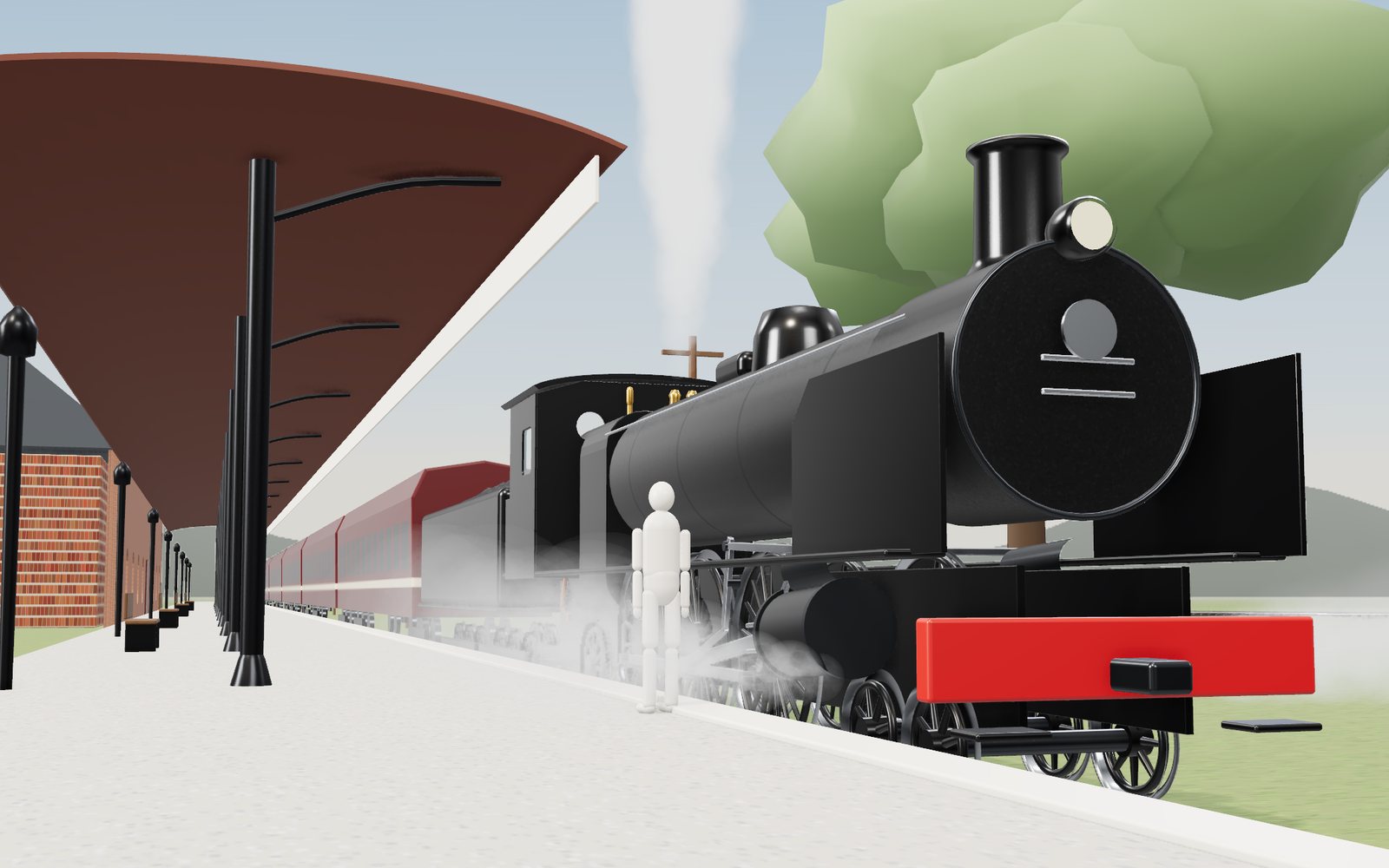
How a steam locomotive works
Mallard's driving wheels are 2.03 m across, taller than most people, and at its record 126 mph they turned almost nine times a second.
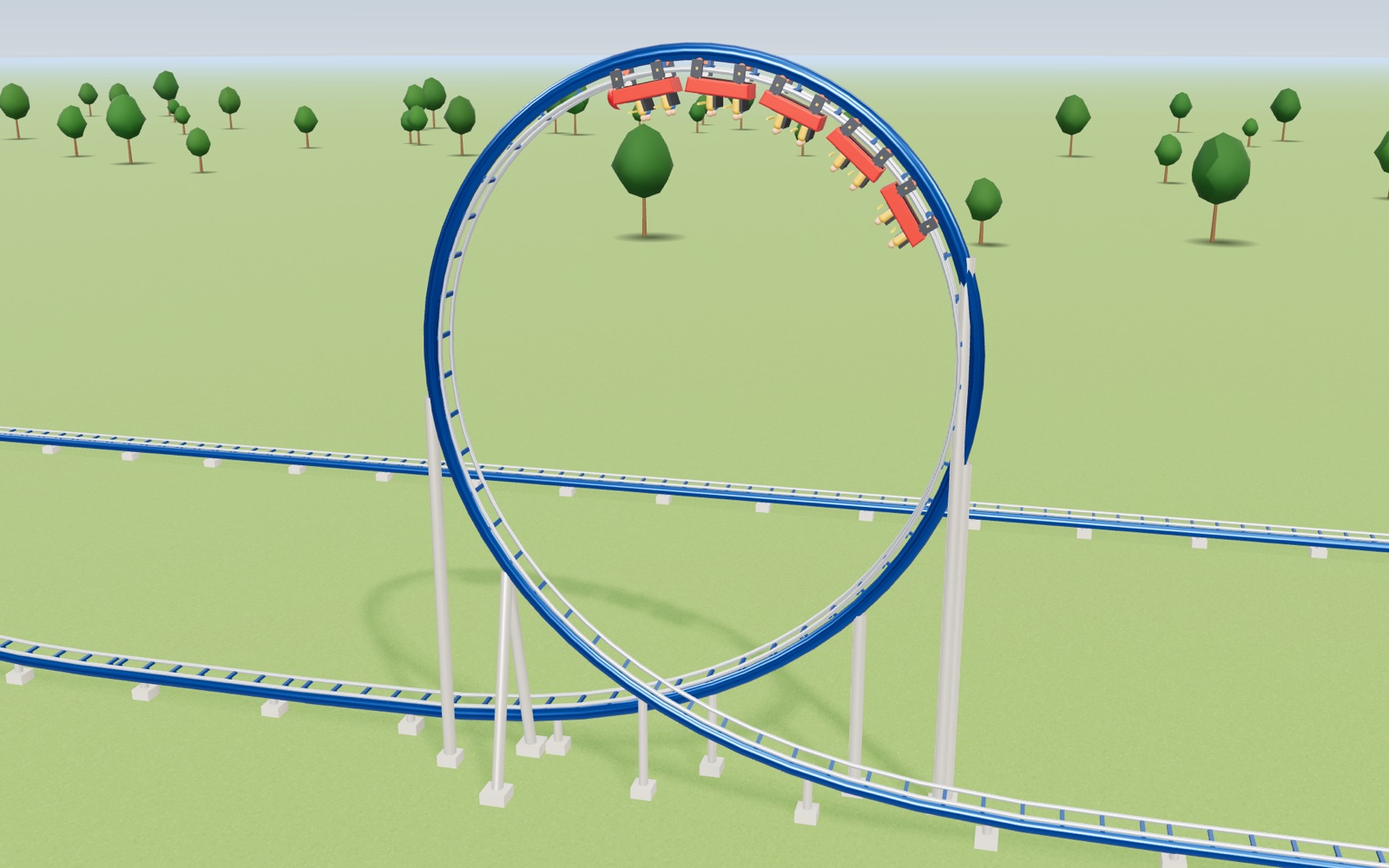
Roller coaster physics: how roller coasters work
A train that creeps over a 42 m lift hill at 3 m/s is doing 99 km/h at the bottom, and nothing but gravity has pushed it.
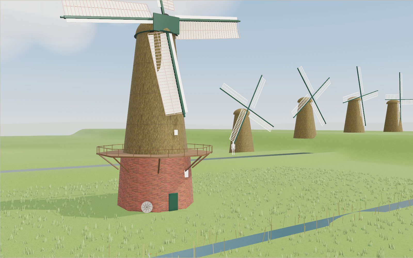
How windmills and watermills work
The sails of a Dutch mill are as wide as an eight-storey building is tall, and at 7 m/s they still take only about a fifth of the wind.