FIG. 41How It Works
How a jet engine works: where an airliner’s thrust comes from
In an airliner's turbofan only one kilogram of air in eleven passes through the flame. Six other kinds of jet engine split the work differently, and you can open each one here.
This device cannot show the 3D model. You can read the guide steps below as text.
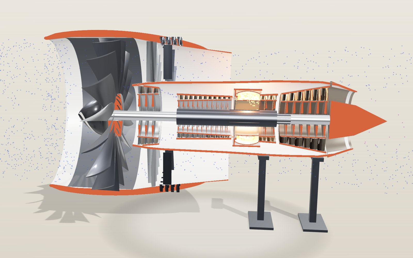
1 / 17 One turbofan, cut along its axisThe half facing you is cut away; the red faces are the cut. Blue dots are cold air and turn purple, orange and red as it heats. The readout gives thrust, fuel and spool speeds.
Drag to turn. Scroll or pinch to zoom.
What the model shows
An airliner’s turbofan gets most of its thrust from the large fan pushing air around the hot core. The core burns fuel and drives turbines, which turn the fan through a shaft. Other jet engine types divide their power differently between exhaust, fans and propellers.
Stand behind an airliner at take-off and it feels as if the engines are blasting fire. Most of what hits you is cold air. In a modern airliner engine only about one kilogram of air in eleven goes through the flame, and the big fan at the front pushes the rest straight back around the hot core. A fighter engine does almost the opposite, a helicopter engine hardly makes a jet at all, and a ramjet has no moving parts. This exhibit puts seven of them on the same stand so you can see how each one shares out the same job.
Each model is cut in half along its axis. The half facing you has been removed, and the red faces are where it was cut. The first one you see is a two-shaft, high-bypass turbofan whose layout follows the stage counts GE Aerospace publishes for its GE9X: one fan stage, a three-stage booster, an eleven-stage high-pressure compressor, two high-pressure turbine stages and six low-pressure turbine stages. The Engine type slider, or the list in Controls, swaps it for a turbojet, a low-bypass fighter engine with an afterburner, a geared turbofan, a turboprop, a turboshaft and a ramjet that turns into a scramjet above Mach 5.
The sizes, airflows and temperatures are model values chosen to be typical of each kind. They are not any manufacturer's performance data. Where the exhibit quotes a real engine, the figure comes from its type certificate data sheet, the document an aviation authority issues when it approves the engine, or from the maker's own page, and the source is named next to it.
The dots are air. Blue dots are cold, and they turn purple, orange and red as the air is squeezed and burned. The small readout shows the thrust (or shaft power), the fuel burned, the fuel per unit of thrust and the shaft speeds. More opens the airflow, jet speeds, outside air and a chart of pressure and temperature row by row through the core. Below the controls there is a lab: the seven engines, a start sequence, six tasks to try, the thrust equation with live numbers, two charts, a side-by-side comparison and a list of 45 real engines, milestones and certification tests.
Why most of the air goes around the core
Any engine that pushes an aircraft forward does it by throwing air backwards. The force depends on how much air it throws each second and how much faster that air leaves than it arrived. There are two ways to get the same force: throw a small amount of air very fast, or a large amount of air a little faster.
The second way wastes far less energy. The kinetic energy left in the jet grows with the square of its speed, while the thrust grows only in proportion to it. A slow, wide jet leaves less energy behind in the air for the same push.
A turbofan does this by splitting the airflow. The inner part, the core, is a complete gas turbine with a compressor, a combustor and turbines. It burns fuel and makes power. Most of that power is not used to make a fast jet. A second turbine takes it out of the hot gas and uses it to turn the fan, which gives a gentle push to a much larger mass of air. NASA's Glenn Research Center defines the bypass ratio as the air flowing around the core divided by the air flowing through it. In the model the core takes 120 kg of air a second, and at a bypass ratio of 10 the fan sends 1,200 kg a second around it.
Pressure and temperature, row by row
The core works on the Brayton cycle, the same cycle as every gas turbine. Air is compressed, heated at roughly constant pressure, then expanded. The chart under More follows the air through each row of blades.
- Compression. Behind the fan, the three booster stages raise the core pressure 1.9 times. The eleven high-pressure stages then multiply it by 22, about 1.32 times per stage. The overall pressure ratio in the model is 41.8, so air that came in at 1 bar leaves the compressor at 42 bar. Squeezing it heats it as well: it leaves at 927 K (about 650 °C) before any fuel is added.
- Combustion. Fuel nozzles spray kerosene into a ring-shaped chamber. The gas heats to 1,700 K while its pressure falls by only about 5 percent. In the chart this is the narrow band where the temperature line jumps and the pressure line stays almost flat.
- Expansion. The hot gas then expands through the turbines. Each turbine row takes some work out of the gas, and its pressure and temperature fall row by row. Whatever pressure is left at the end pushes the gas out of the nozzle.
Move the throttle and the whole chart moves. At full throttle the compressor reaches 42 bar and the turbine entry 1,700 K. At half throttle both peaks are lower, and the readout shows about half the air, 1.30 kg/s of fuel and 155 kN of thrust.
The Pressure ratio and Turbine entry temperature sliders change the two numbers that decide how good a core can be. An ideal Brayton cycle with a pressure ratio of 41.8 would turn 65.6 percent of the fuel's heat into jet energy (η = 1 − 1/r^0.286). With the losses in the model's compressors and turbines the figure is 39.6 percent at full throttle on the ground. A higher turbine temperature lets the same core make more power from each kilogram of air, which is why so much of the engine's cost goes into the turbine blades.
Two shafts at two speeds
A fan works best at a fairly low speed. Its tips are a long way from the axis, and if they move too fast the shock waves on the blades waste energy and make noise. The small compressor blades in the core need the opposite, a high speed. One shaft cannot suit both.
So a turbofan has two shafts, one inside the other. The low-pressure shaft runs from the six-stage low-pressure turbine at the back all the way forward to the fan and the booster. Around it, the hollow high-pressure shaft joins the two high-pressure turbine stages to the high-pressure compressor. NASA's turbofan page describes it the same way: the fan shaft passes through the core shaft, an arrangement called a two-spool engine.
In the model the low-pressure shaft turns at up to 2,500 rpm and the high-pressure shaft at up to 11,000 rpm. GE Aerospace lists 2,510 rpm and 11,119 rpm for the GE9X. On screen both run very slowly, but the ratio between them is kept.
Even at 2,500 rpm the fan tips move fast. With a fan radius of 1.61 m the tip speed is 2π × 1.61 × 2,500 / 60 = 422 m/s, about 1.24 times the speed of sound at sea level. A 134-inch fan at 2,510 rpm comes out at 447 m/s by the same sum.
The thrust equation, worked out
For one stream of air the thrust is
F = ṁ (v_e − v_0)
where ṁ is the mass of air per second, v_e is the speed of the jet leaving the nozzle and v_0 is the speed of the air arriving (the flight speed). NASA's thrust page adds a pressure term for a nozzle that does not expand the gas fully. The model's nozzles expand it fully, so that term is zero.
A turbofan has two streams, so the lab adds two terms. The core stream also carries the fuel, which is why it is multiplied by (1 + f), where f is the fuel-to-air ratio. With the engine standing still, full throttle and a bypass ratio of 10:
- Core: 120 kg/s × (1.025 × 331 m/s − 0) = 40.7 kN
- Bypass: 1,200 kg/s × (272 m/s − 0) = 326.6 kN
- Total: 367.3 kN
The core jet is the faster of the two, but the bypass stream carries ten times as much air and gives 89 percent of the thrust. The fuel flow is 3.01 kg/s, about 10.8 tonnes an hour at full power. Dividing fuel flow by thrust gives the thrust-specific fuel consumption, TSFC, the number engineers use to compare engines: 3.01 kg/s ÷ 367.3 kN = 8.2 g of fuel per kilonewton each second.
For comparison, the Rolls-Royce Trent 1000-C on the Boeing 787 is certified for 331.4 kN of take-off thrust, and the GE90-115B for 513.95 kN. The first task in the lab asks you to set the model to the Trent figure with the throttle.
Bypass ratio, thrust and fuel
The bypass slider keeps the core exactly the same (same airflow, same pressures, same fuel) and changes only how much air the fan handles. For each setting the model picks the fan pressure ratio that gives the most thrust. The fan and nacelle grow as the ratio rises, because more air needs a bigger fan face.
| Bypass ratio | Fan diameter | Thrust, static | Core jet | TSFC |
|---|---|---|---|---|
| 4 | 2.3 m | 252.5 kN | 477 m/s | 11.9 g/kN·s |
| 5 | 2.5 m | 275.2 kN | 439 m/s | 10.9 g/kN·s |
| 8 | 2.9 m | 333.7 kN | 364 m/s | 9.0 g/kN·s |
| 10 | 3.2 m | 367.3 kN | 331 m/s | 8.2 g/kN·s |
| 12 | 3.5 m | 397.9 kN | 306 m/s | 7.6 g/kN·s |
The same core built as a plain turbojet makes 122 kN on the same fuel, a third of the turbofan's thrust. The second chart in the lab draws the whole curve and marks the current setting.
In flight the picture changes, and the flight speed slider shows how. The engine must first accelerate the incoming air up to its own speed before it can push, so every kilogram of air costs v_0 of thrust. At Mach 0.8 at sea level (272 m/s), the turbofan makes 200.9 kN and the same core as a turbojet 126.3 kN. The turbofan still needs far less fuel for each newton: 19.0 against 30.5 g/kN·s. The reason is propulsive efficiency, roughly 2 / (1 + v_e / v_0). A jet only slightly faster than the aircraft wastes little energy, and the model gives 83.5 percent for the turbofan against 43.6 percent for the turbojet.
Why not a bypass ratio of 30? Each step up brings less gain, as the curve flattens. The fan gets heavier, the nacelle gets bigger and draggier, and the engine has to fit under the wing. The model leaves weight and drag out, so its curve keeps rising. The ratios published for today's large engines sit around 10 to 12: GE gives about 10:1 for the GE9X, and Pratt & Whitney up to 12:1 for its geared fan.
Why thrust falls with altitude
Airliners cruise at 10 to 12 km, where the air is thin. The model uses the International Standard Atmosphere: the temperature falls 6.5 K for each kilometre up to 11 km, then stays at 216.65 K (−56.5 °C) up to 20 km. At 11 km the pressure is 22.6 kPa and the density 0.364 kg/m³, 29.7 percent of the sea-level value.
An engine moves a volume of air each second that depends on its size and speed, so the mass of air it handles falls roughly with the density. The model follows the rule engine designers use: at the same shaft speed the flow scales with the inlet pressure divided by the square root of the inlet temperature. Climb from sea level to 11 km at Mach 0.8 and the airflow falls from 1,895 kg/s to 488 kg/s. The thrust falls from 200.9 kN to 79.5 kN, to 39.6 percent of its sea-level value.
That is a little better than the density ratio, because cold air is easier to compress: the same compressor reaches a higher temperature ratio in the turbine, and the thermal efficiency rises from 40 to 46.5 percent. The fuel per thrust improves too, from 19.0 to 15.9 g/kN·s. This is why airliners climb as high as their weight allows. The altitude chart in the lab draws thrust and air density side by side, and the fourth task asks you to explain the drop.
Seven kinds of jet engine
All seven are gas turbines except the last, and all seven work on the same idea: squeeze air, heat it, let it out faster than it came in. They differ in what they do with the energy left after the core has driven its own compressor.
Turbojet
The first jet engines put all the air through the flame. Frank Whittle's bench engine first ran on 12 April 1937. The Smithsonian's W.1X, the engine used in the Gloster E.28/39's taxiing trials, had a single-stage double-entry centrifugal compressor, ten reverse-flow combustion chambers and a one-stage axial turbine, and it made 5,516 N at 17,750 rpm on 254 kg of engine. Hans von Ohain's engine flew first, in the Heinkel He 178 on 27 August 1939. Both men used centrifugal compressors, which throw the air outward with an impeller much like a vacuum cleaner.
The model draws this layout: an impeller, ten straight can combustors on a ring, a one-stage turbine and a jet pipe. Its default pressure ratio is 4 and its turbine entry temperature 1,050 K, close to what the materials of the time could take. Standing still it makes 12.7 kN from 22 kg of air a second and burns 31.5 g of fuel per kN each second, almost four times the high-bypass turbofan. Raise the pressure ratio and turbine temperature and the same layout becomes a supersonic engine: Pratt & Whitney's J58, which powered the SR-71, was an afterburning turbojet with an eight-stage axial compressor and a two-stage turbine, rated by the Smithsonian at 133.44 kN.
Low-bypass turbofan with afterburner
A fighter needs a thin engine that makes a fast jet, because it flies fast. The model's fighter engine has a three-stage fan, a little bypass air (0.4 kg around the core for each kg through it), a nine-stage compressor, one high-pressure and two low-pressure turbine stages, and a long jet pipe. The bypass air joins the core stream in a mixer behind the turbine.
The jet pipe is where the afterburner sits: fuel spray rings and V-shaped flame holders that keep a flame alight in fast-moving gas. Turn on Afterburner and the model burns fuel again, at about 2,050 K, behind the turbine. At sea level the thrust rises from 90.5 kN to 112.9 kN, and the fuel from 2.27 kg/s to 5.21 kg/s, 2.3 times as much for a quarter more thrust. At 11 km and Mach 1.6 the gain is larger, 1.7 times the thrust for 2.5 times the fuel. Burning at low pressure behind the turbine gets less work out of each kilogram of fuel, so pilots use it for take-off, climbing and combat, and the nozzle has to open wider to let the hotter, larger volume of gas out. Concorde's Olympus 593 was the only afterburning turbojet in airline service; the Museum of Flight notes it was lit for take-off.
High-bypass turbofan
This is the engine described above, and the one on most airliners. The bypass ratio slider runs from 4 to 12 for it, the flight speed up to Mach 0.9 and the altitude up to 15 km.
Geared turbofan
The fan wants to turn slowly, the low-pressure turbine quickly. In a direct-drive turbofan the two share a shaft, so the turbine needs many stages to do its work at low speed. Pratt & Whitney's GTF puts a gearbox between them. The company lists a 3:1 gear ratio, fans up to 81 inches across, a bypass ratio up to 12:1 and a fan speed 40 percent lower, with three low-pressure compressor stages, eight high-pressure stages, two high-pressure turbine stages and three low-pressure turbine stages.
The model draws a sun gear on the fast shaft, five planets in a carrier and a ring gear driving the fan. On screen the booster and low-pressure turbine spin about three times faster than the fan. The core in this model is smaller (25 kg/s) and the fan relatively bigger; at sea level standing still it makes 86.2 kN on 0.67 kg/s of fuel, 7.8 g/kN·s. The PW1133G-JM, a production geared fan, is certified for 147.28 kN.
Turboprop
Take the fan out of its duct, make it much bigger and slower, and you have a propeller. A turboprop's core drives a free power turbine on its own shaft, and that shaft runs forward through the middle of the engine to a reduction gearbox, because a propeller has to turn far more slowly than a small turbine. The type certificate for the PT6A-100 series lists exactly that chain: a two-stage reduction gearbox, a single-stage power turbine, a single-stage compressor turbine and a four-stage compressor, three axial stages and one centrifugal.
The model has two centrifugal compressors, a combustor, two gas-generator turbines, a two-stage power turbine and a six-blade propeller 3.93 m across. Standing still it delivers 2,709 kW to the propeller. A propeller is rated by power, not thrust, so the readout shows both: 42.8 kN from the propeller (from momentum theory, with a figure of merit of 0.6) and 1.9 kN from the exhaust. The fuel per unit of power is 255 g/kWh. The PW127M on the ATR 72 is certified for 2,051 kW of maximum take-off power. Turboprops are at their best below about 600 km/h; faster than that, the propeller tips approach the speed of sound.
Turboshaft
A turboshaft is a turboprop without the propeller: the power turbine sends nearly everything down the output shaft, and the jet that is left is barely a breeze. The model follows the layout that the type certificate gives for the GE CT7: a five-stage axial and one-stage centrifugal compressor, an annular combustor, a two-stage gas-generator turbine and a free two-stage power turbine whose shaft runs forward through the engine, and an inlet with swirl vanes that throw sand outward before it reaches the compressor. It delivers 1,740 kW at sea level, and the leftover jet makes only 0.6 kN.
Real figures from the type certificates: the Safran Arriel 2D in the H125 helicopter gives 598 kW for take-off, and the GE CT7-8A in the S-92 gives 1,879 kW (2,520 shp) with its output shaft at 21,945 rpm. The main gearbox of the helicopter brings that down to a rotor speed of a few hundred rpm.
Ramjet and scramjet
Above about Mach 3, the air arriving at an engine is already squeezed enough by its own speed. A ramjet drops the compressor and turbine altogether. A cone in the inlet sets up shock waves that slow the air below the speed of sound and raise its pressure; fuel is sprayed in, flame holders keep it alight, and a nozzle accelerates the hot gas out. NASA puts the ramjet's working range at about Mach 3 to Mach 6.
A ramjet makes no thrust standing still, and the model shows that: below Mach 0.3 it cannot run, and the start button explains that a rocket or another engine has to push it first. At Mach 3 and 18 km the model's inlet keeps 81 percent of the total pressure, the jet leaves at 1,636 m/s and the specific impulse is 1,695 s, far better than a rocket's few hundred seconds, because the oxygen comes from the air.
Above Mach 5, slowing the air to subsonic speed would heat it so much that the fuel could barely add any more energy. A scramjet (supersonic-combustion ramjet) keeps the air supersonic all the way through and burns hydrogen in it within a few thousandths of a second. At Mach 7 the air arriving at the model has a stagnation temperature of 2,426 K before any fuel burns. NASA's X-43A flew on hydrogen at Mach 6.8 on 27 March 2004 and at Mach 9.6 on 16 November 2004, launched from a B-52 and boosted by a Pegasus rocket. NASA notes that no flight test has gone faster on an air-breathing engine.
Inside the hottest blade
Press Blade close-up and the stage shows one high-pressure turbine blade on its own. It sits in gas hotter than the melting point of the metal it is made from, so three tricks keep it alive.
- One crystal. Ordinary castings are made of many grains, and the boundaries between grains are the weak spots where cracks start and oxidation creeps in. A NASA report explains that single-crystal nickel superalloys were developed to remove those boundaries, which also lets the alloy do without the grain-boundary strengtheners that lower its melting point. An earlier NASA review of Lewis Research Center work put the gain at about 75 °C of extra working temperature over a conventionally cast blade.
- Cooling from inside. The blade is hollow. Air taken from the compressor, still several hundred degrees cooler than the gas outside, flows through winding passages and leaves through rows of tiny holes on the surface, where it spreads into a thin film that keeps the hot gas off the metal. The model shows four rows of holes and three internal passages.
- A ceramic coat. A thin layer of zirconia stabilized with yttria sits on a metallic bond coat. NASA's history of thermal barrier coatings traces this zirconia-yttria system to its own work, and notes that by 1989 such coatings were being used on turbine blades in airline service. The layer slab beside the blade shows the three layers with their thicknesses exaggerated.
The root is cut in a fir-tree shape so that the blade's pull, many tonnes at full speed, spreads over several teeth in the disc. The type certificate for the PW1100G-JM gives an idea of the limits: 1,083 °C indicated turbine temperature for five minutes at take-off, 1,043 °C continuously. That is measured after the first turbine stages; the gas at the first blades is far hotter.
Reverse thrust
After touchdown an airliner uses its brakes, its spoilers and, at high speed, reverse thrust. On a high-bypass engine the reverser works on the fan stream. The rear of the nacelle slides back and opens a ring of cascade vanes; blocker doors fold into the bypass duct and turn the fan air out through the cascades and forward. Turn on Reverse thrust to see the sleeve move and the dots of fan air turn around. The core jet still points backwards, so the net reverse force is only part of the forward thrust: at 70 percent throttle the model gives 76.9 kN of reverse force.
The type certificate for the Trent XWB says maximum reverse thrust should not be used below 60 knots, when idle reverse should be selected, and reverse should be fully deselected below 40 knots. At low speed the reversed air can be swallowed again by the inlet, along with debris from the runway. The landing task in the lab uses that rule: a 200-tonne airliner touching down at 140 knots on a wet runway (braking at 0.15 g) needs 1,765 m on brakes alone. With both engines in reverse at 70 percent throttle until 60 knots the model stops in 1,091 m.
The turbojet model uses the older target reverser: two buckets close behind the nozzle and turn the whole jet. On the turboprop the propeller blades twist past flat pitch so they push air forwards.
Starting an engine
A jet engine cannot start itself, because its compressor has to be turning before it can supply air for the fire that drives it. FAA's powerplant handbook describes the usual arrangement on airliners: an air turbine starter on the accessory gearbox, driven by compressed air from the auxiliary power unit (APU) in the tail, from a ground cart or from an engine already running.
Press Start in the lab and the model goes through five steps. Bleed air arrives; the starter spins the high-pressure spool; at about 20 percent N2 the fuel opens and the igniters spark; the flame catches and the exhaust temperature jumps (the light-off); the starter cuts out and the engine accelerates to idle on its own at about 60 percent N2. The percentages are model values, close to the ones pilots see on many engines. The crew watches the exhaust temperature closely during this time, since a start with too little airflow can overheat the turbine.
Birds, ice, hail and a lost blade
Before an engine type can fly with passengers it must pass tests set out in Part 33 of the US federal aviation regulations; EASA's CS-E sets equivalent ones.
- Birds (14 CFR 33.76). The engine runs at full take-off power and swallows one large bird at 200 knots, aimed at the most critical spot on the first-stage blades. The bird's weight depends on the inlet throat area: 1.85 kg below 1.35 m², 2.75 kg up to 3.90 m², 3.65 kg above that. The power lever may not be moved for 15 seconds afterwards. Further tests use flocks of small and medium birds. The model fan, 3.2 m across, has a face area of 8.2 m², so it falls in the 3.65 kg row, which the bird task asks you to work out.
- Ice (14 CFR 33.77). Ice thrown into the engine may not cause a lasting loss of thrust or make the engine shut down.
- Rain and hail (14 CFR 33.78). Hailstones of 25 mm and 50 mm are fired in at the highest airspeed up to 4,500 m, one of each for every 150 square inches of inlet, half of them aimed at the most critical part of the inlet.
- A lost blade (14 CFR 33.94). At the highest permitted rpm a fan blade, and in a second test a turbine blade, is released at its root. The casing must hold the pieces, with no fire and no failure of the engine mounts, for at least 15 seconds.
GE Aerospace says the GE9X went through more than 31,000 test cycles, with over 9,000 endurance cycles and 2,300 dust ingestion cycles, and shows ice testing at its Peebles site in Ohio.
Engines in the comparison list
The lab list has 45 entries. The engines with certified figures, from EASA's type certificate data sheets:
| Engine | Aircraft | Take-off rating | Weight |
|---|---|---|---|
| GE90-115B | Boeing 777 | 513.95 kN | 8,761 kg |
| Trent XWB-97 | Airbus A350-1000 | 431.5 kN | 7,549 kg |
| GP7277 | Airbus A380 | 357.15 kN | |
| GEnx-1B76 | Boeing 787 | 349.2 kN | |
| Trent 1000-C | Boeing 787 | 331.4 kN | |
| CF6-80C2B1F | Boeing 747-400 | 254.26 kN | |
| PW1133G-JM | Airbus A321neo | 147.28 kN | 2,857.6 kg |
| LEAP-1A35A | Airbus A321neo | 143.05 kN | 2,990 kg with fluids |
| CFM56-7B27 | Boeing 737 | 121.43 kN | 2,386 kg |
| V2527-A5 | Airbus A320 | 110.31 kN | |
| PW127M | ATR 72 | 2,051 kW | |
| Arriel 2D | H125 | 598 kW |
Show on any of these sets the model to that engine's type and scales its airflow so that the model's sea-level thrust (or shaft power) matches the certified rating. From there the throttle, altitude and speed sliders show what the model predicts for the rest of the flight. The weights are as each data sheet states them, so they do not all include the same equipment.
How this model differs from a real engine
- The cycle is a one-dimensional textbook calculation with fixed component efficiencies and constant gas properties. Real engines are designed with detailed performance codes.
- The throttle law (how pressure, airflow and temperature fall when you throttle back) is a simple model. The lowest throttle setting is still well above a real ground idle.
- Turbine blades in real engines are cooled by air taken from the compressor, and some air is bled off for the cabin. The cycle ignores both.
- Fan weight, nacelle drag and the losses of installing the engine on the wing are left out, which is why the model's bypass curve keeps rising.
- The propeller and rotor use momentum theory, which gives a fair idea of static thrust and lift but not their real design curves.
- The ramjet's inlet losses follow a standard curve and the scramjet's combustor is a single number; real hypersonic inlets are designed for one speed.
- Each engine is drawn at roughly the same size on the stand. A turboshaft is much smaller than an airliner fan in real life.
- The air dots in the core are drawn denser than the bypass dots, so that the core flow stays visible.
From the first turbojets to fans wider than a fuselage
Whittle patented the jet engine in 1932, and his British patent GB 471,368, first filed on 4 March 1936, already described the principle of a bypass engine. His Whittle Unit first ran on 12 April 1937. In Germany, von Ohain's engine flew in the Heinkel He 178 on 27 August 1939. The Gloster E.28/39 with Whittle's W.1 made its first official flight on 15 May 1941, and the W.1X and the drawings of the W.2B went to General Electric that October. GE's version, the I-A, flew the first American jet aircraft, the Bell XP-59A, on 2 October 1942.
The first production turbofan, the Rolls-Royce Conway, had a bypass ratio of only 0.3. The jump came in the late 1960s, when General Electric built the TF39, the first high-bypass turbofan, with a bypass ratio of 8 for the Lockheed C-5 Galaxy. Pratt & Whitney's JT9D, first run in 1966, powered the Boeing 747 on its first flight on 9 February 1969 and was the first of the very large high-bypass engines in airline service. Its civil rival from GE, the CF6, followed on the DC-10 in 1971.
At the fast end, two afterburning J58s drove each SR-71, and Concorde's four Olympus 593s, 38,050 lb each, carried passengers at a cruise speed of 1,354 mph until the last British Airways flight on 24 October 2003.
Since then fans have kept growing. GE says the GE90 was the first engine with composite fan blades. The GE9X, certified by the FAA in September 2020, has 16 composite blades, a bypass ratio of about 10, an overall pressure ratio of 60 and 10 percent lower fuel per thrust than the GE90-115B. Pratt & Whitney's geared turbofan entered service in 2016; MTU, which builds part of it, lists the PW1100G-JM for the Airbus A320neo family. And in 2004 NASA's X-43A showed that a scramjet can fly at Mach 9.6.
Questions
Why is it called a turbofan?
Because a turbine drives a fan. The core is a gas turbine like any jet engine, but most of its power goes through the low-pressure turbine and shaft to the fan at the front.
What does bypass ratio mean?
It is the air that flows around the core divided by the air that flows through it. At a bypass ratio of 10, ten kilograms of air pass through the fan and bypass duct for every kilogram that enters the compressor.
Does most of the thrust come from the hot exhaust?
Not on an airliner. In this model at take-off the bypass air gives 89 percent of the thrust and the core jet 11 percent. On the fighter engine it is the other way round: 76.4 of its 90.5 kN come from the core.
Why does the engine need two shafts?
The large fan has to turn slowly enough that its tips do not go far beyond the speed of sound. The small blades of the high-pressure compressor work best at high speed. Two shafts let each run at its own speed: in the model 2,500 rpm and 11,000 rpm. A geared fan goes one step further and adds a gearbox.
How hot does it get inside?
In the model the gas reaches 1,700 K (about 1,430 °C) as it leaves the combustor. That is the hottest point in the engine. Real turbine blades survive it because they are single crystals, hollow and cooled from inside, and coated with ceramic.
Why does a jet engine make less thrust in flight than on the ground?
Two reasons. Thrust depends on the difference between the jet speed and the flight speed, so speed alone takes some away: at Mach 0.8 at sea level the turbofan falls from 367.3 kN to 200.9 kN. Height takes more, because thin air means less mass through the engine: at 11 km the same engine makes 79.5 kN.
What is TSFC?
Thrust-specific fuel consumption: fuel burned per second divided by thrust. NASA's Glenn Research Center uses it as the measure of an engine's fuel efficiency, and lower is better. The model reads 8.2 g/kN·s for the high-bypass turbofan standing still and 31.5 g/kN·s for the early turbojet.
Why does an afterburner use so much fuel?
It burns fuel in gas that has already passed the turbine, where the pressure is low. Heat added at low pressure turns into less jet energy than heat added at high pressure in the combustor. In the model the afterburner adds a quarter to the thrust at sea level for 2.3 times the fuel.
Why do turboprops and helicopters measure power, not thrust?
Their turbine turns a shaft, and the propeller or rotor turns that power into thrust or lift in its own way, depending on its size and speed. The type certificate rates the engine by the power at the shaft: 2,051 kW for the PW127M, 598 kW for the Arriel 2D.
Can a ramjet start on the ground?
No. Without forward speed nothing squeezes the air, so there is no pressure to burn at. Ramjet vehicles are launched by a rocket or carried by an aircraft first; the X-43A rode a Pegasus rocket from under a B-52.
What happens if a bird hits the fan?
Engines are tested for it. A large bird of up to 3.65 kg is fired into an engine running at take-off power at 200 knots, and the engine must keep running safely. Flocks of smaller birds are tested as well, and in a separate test a whole fan blade is released at full speed and the casing must hold it.
How does an engine start?
Compressed air from the APU drives a small air turbine on the gearbox, which spins the high-pressure spool. Once the compressor is turning fast enough to feed the combustor, fuel and the igniters are switched on, the flame lights, and the engine accelerates the rest of the way by itself.
Why do airliners cruise so high if the engines make less thrust there?
The aircraft needs less thrust there too, because the thin air also means less drag. The engine itself gets more efficient in cold air: in the model the fuel per thrust at Mach 0.8 falls from 19.0 g/kN·s at sea level to 15.9 g/kN·s at 11 km.
Why not make every engine a turbofan with a huge fan?
A bigger fan needs a bigger, heavier nacelle with more drag, and it has to fit under the wing with enough ground clearance. Fast aircraft also need a fast jet: a slow fan stream is efficient only when the aircraft itself is slower than the jet. That is why fighters use low bypass ratios and the fastest aircraft use turbojets and ramjets.
Terms
- Core: the inner gas turbine (compressor, combustor and turbines) that burns the fuel.
- Bypass ratio: mass of air going around the core divided by mass going through it.
- Spool: a shaft with the compressor and turbine stages fixed to it. The airliner model has two; the turboprop has three.
- Stage: one row of rotating blades and the row of fixed vanes next to it.
- Overall pressure ratio: pressure at the compressor exit divided by pressure at the inlet.
- Turbine entry temperature: gas temperature leaving the combustor, the hottest point in the engine.
- TSFC: fuel flow divided by thrust.
- Propulsive efficiency: the share of the jet's energy that goes into moving the aircraft.
- Afterburner (reheat): a second burner in the jet pipe behind the turbine.
- Free power turbine: a turbine on its own shaft that drives a propeller or rotor.
- Type certificate data sheet (TCDS): the document in which an aviation authority records an approved engine's ratings and limits.
- ISA: International Standard Atmosphere, the agreed table of temperature, pressure and density with height.
- Light-off: the moment the fuel in the combustor first catches during a start.
- Nacelle: the streamlined casing around the engine.
Sources
- NASA Glenn Research Center, Turbofan Thrust (bypass ratio, two-spool layout, thrust of two streams). https://www.grc.nasa.gov/www/k-12/airplane/turbfan.html
- NASA Glenn Research Center, Turbofan Engine. https://www.grc.nasa.gov/www/k-12/airplane/aturbf.html
- NASA Glenn Research Center, Turbojet Engine. https://www.grc.nasa.gov/www/k-12/airplane/aturbj.html
- NASA Glenn Research Center, Turboprop Thrust. https://www.grc.nasa.gov/www/k-12/airplane/turbprp.html
- NASA Glenn Research Center, Turbine Engine Thermodynamic Cycle: Brayton Cycle. https://www.grc.nasa.gov/www/k-12/airplane/brayton.html
- NASA Glenn Research Center, Beginner's Guide to Aeronautics, Thrust Force (thrust equation). https://www1.grc.nasa.gov/beginners-guide-to-aeronautics/thrust-force/
- NASA Glenn Research Center, Specific Fuel Consumption. https://www.grc.nasa.gov/www/k-12/airplane/sfc.html
- NASA Glenn Research Center, Earth Atmosphere Model (standard atmosphere layers). https://www.grc.nasa.gov/www/k-12/airplane/atmosmet.html
- NASA Glenn Research Center, Ramjet and Scramjet. https://www1.grc.nasa.gov/beginners-guide-to-aeronautics/ramjet/ and https://www1.grc.nasa.gov/beginners-guide-to-aeronautics/scramjet/
- NASA, X-43A Hyper-X (Mach 6.8 on 27 March 2004, Mach 9.6 on 16 November 2004, ramjet range). https://www.nasa.gov/reference/x-43a/
- NASA, R. A. Miller, History of Thermal Barrier Coatings for Gas Turbine Engines, NASA/TM-2009-215459. https://ntrs.nasa.gov/api/citations/20090018047/downloads/20090018047.pdf
- NASA, Effect of Crystal Orientation on Analysis of Single-Crystal, Nickel-Based Turbine Blade Superalloys (grain boundaries, single-crystal blades). https://ntrs.nasa.gov/api/citations/20000037784/downloads/20000037784.pdf
- NASA, Progress in Materials and Structures at Lewis Research Center (single-crystal blades about 75 °C hotter). https://ntrs.nasa.gov/api/citations/19810004471/downloads/19810004471.pdf
- Federal Aviation Administration, Aviation Maintenance Technician Handbook, Powerplant (FAA-H-8083-32B), chapter 5, Engine Starting Systems. https://www.faa.gov/regulationspolicies/handbooksmanuals/aviation/faa-h-8083-32b-chapter-5-engine-starting-systems
- eCFR, 14 CFR 33.76 Bird ingestion. https://www.ecfr.gov/current/title-14/chapter-I/subchapter-C/part-33/subpart-E/section-33.76
- eCFR, 14 CFR 33.77 Foreign object ingestion, ice. https://www.ecfr.gov/current/title-14/chapter-I/subchapter-C/part-33/subpart-E/section-33.77
- eCFR, 14 CFR 33.78 Rain and hail ingestion. https://www.ecfr.gov/current/title-14/chapter-I/subchapter-C/part-33/subpart-E/section-33.78
- eCFR, 14 CFR 33.94 Blade containment and rotor unbalance tests. https://www.ecfr.gov/current/title-14/chapter-I/subchapter-C/part-33/subpart-E/section-33.94
- EASA, type certificate data sheet IM.E.002, GE90 series (ratings, weight, rating conditions). https://www.easa.europa.eu/en/downloads/7799/en
- EASA, type certificate data sheet E.111, Trent XWB series (ratings, weights, reverse-thrust limits). https://www.easa.europa.eu/en/downloads/7635/en
- EASA, type certificate data sheet IM.E.093, PW1100G-JM series (ratings, weight, turbine temperature limits). https://www.easa.europa.eu/en/downloads/20016/en
- EASA, type certificate data sheet E.110, LEAP-1A and LEAP-1C series. https://www.easa.europa.eu/en/downloads/20086/en
- EASA, type certificate data sheets for the GEnx (IM.E.102), Trent 1000 (E.036), GP7200 (IM.E.026), CF6-80, CFM56-7B (E.004), CFM56-5B (E.003), CFM56-2/-3, V2500 (IM.E.069), PW100 (IM.E.041), Arriel 2 (E.001) and CT7 (IM.E.010) series. https://www.easa.europa.eu/en/document-library/type-certificates
- EASA, type certificate data sheet IM.E.094, PT6A-100 series (layout), copy held by the UK Civil Aviation Authority. https://www.caa.co.uk/Documents/Download/3939/984aa08e-5352-4da9-824b-309ec7cec37d/2927
- GE Aerospace, GE9X (stage counts, bypass and pressure ratios, spool speeds, composite blades, test cycles, certification). https://www.geaerospace.com/commercial/aircraft-engines/ge9x
- GE Aerospace, GE90 (first composite fan blades). https://www.geaerospace.com/commercial/aircraft-engines/ge90
- Pratt & Whitney (RTX), GTF engine family (3:1 gear, 81-inch fan, 12:1 bypass, stage counts). https://www.rtx.com/en/prattwhitney/products/commercial-engines/gtf/family
- MTU Aero Engines, Pratt & Whitney GTF engine (entry into service 2016, applications). https://www.mtu.de/engines/commercial-aircraft-engines/narrowbody-and-regional-jets/gtf-engine-family/
- Aircraft Commerce, issue 87 (2013), CFMI reveals more LEAP programme details (fan diameters and bypass ratios of the LEAP and CFM56). https://www.aircraft-commerce.com/wp-content/uploads/aircraft-commerce-docs/Developments/2013/ISSUE%2087_DEVELOP.pdf
- Smithsonian National Air and Space Museum, Whittle W.1X Engine. https://airandspace.si.edu/collection-objects/whittle-w1x-engine/nasm_A19500082000
- Smithsonian National Air and Space Museum, Pratt & Whitney JT9D-1GT2 Turbofan Engine, Cutaway. https://airandspace.si.edu/collection-objects/pratt-whitney-jt9d-1gt2-turbofan-engine-cutaway/nasm_A19820085000
- Smithsonian National Air and Space Museum, Pratt & Whitney J58 (JT11D-20) Turbojet Engine. https://airandspace.si.edu/collection-objects/pratt-whitney-j58-jt11d-20-turbojet-engine/nasm_A19920006000
- Smithsonian National Air and Space Museum, Rolls-Royce Conway RCo.12 Mark 509 Turbofan Engine (the first production bypass engine). https://airandspace.si.edu/collection-objects/rolls-royce-conway-rco12-mark-509-turbofan-engine/nasm_A19870225000
- Shannon Aviation Museum, Rolls Royce Conway (bypass ratio of 0.30). https://shannonaviationmuseum.com/exhibitions/rolls-royce-conway/
- University of Cambridge, Department of Engineering, A tribute to Frank Whittle (He 178 on 27 August 1939, W.1 on 15 May 1941). https://www-g.eng.cam.ac.uk/125/achievements/whittle/whitt-r.htm
- Science Museum Group, Gloster-Whittle E28/39 jet aeroplane, built 1941. https://collection.sciencemuseumgroup.org.uk/objects/co29600/gloster-whittle-e28-39-jet-aeroplane-built-1941
- The Museum of Flight, Concorde (Olympus 593 Mk 610, 38,050 lb, reheat for take-off). https://www.museumofflight.org/exhibits-and-events/aircraft/concorde
- Google Patents, GB471368A, Frank Whittle, Improvements relating to the propulsion of aircraft, priority 4 March 1936 (bypass principle). https://patents.google.com/patent/GB471368A/en
- GlobalSecurity.org, TF39-GE-1 (the first high-bypass turbofan, installed on the C-5A; the CF6 was its commercial derivative). https://www.globalsecurity.org/military/systems/aircraft/systems/tf39.htm
- International Directory of Company Histories, GE Aircraft Engines, Encyclopedia.com (TF39 bypass ratio of eight; the CF6 on the DC-10 in 1971). https://www.encyclopedia.com/books/politics-and-business-magazines/ge-aircraft-engines
- Calculations on this page: one-dimensional gas-turbine, propeller and ramjet cycles with model values (high-bypass core flow 120 kg/s, overall pressure ratio 41.8, turbine entry 1,700 K, kerosene 43 MJ/kg, hydrogen 120 MJ/kg). Pages checked 18 October 2026.
More exhibits
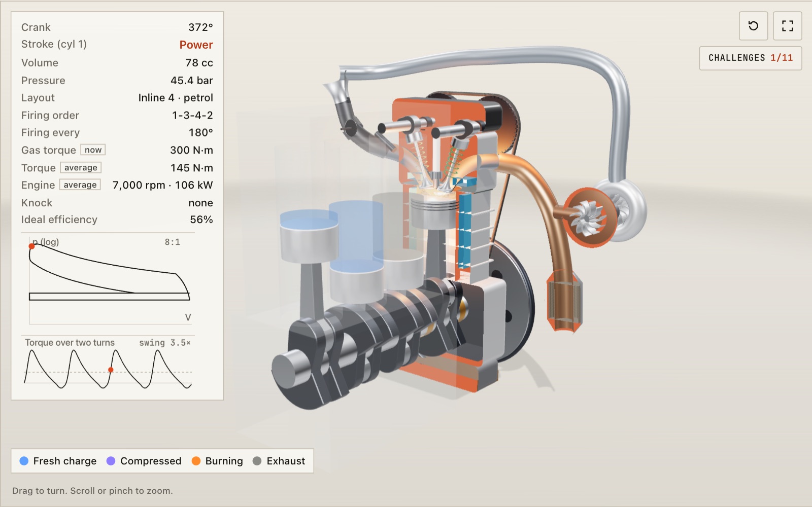
How a four-stroke engine works: two crank turns per cycle
At 3,000 rpm each cylinder fires 25 times a second. Here the engine turns slowly enough to follow every stroke, laid out as anything from a single to a V8 with its own firing order.
How a steam locomotive works
Mallard's driving wheels are 2.03 m across, taller than most people, and at its record 126 mph they turned almost nine times a second.
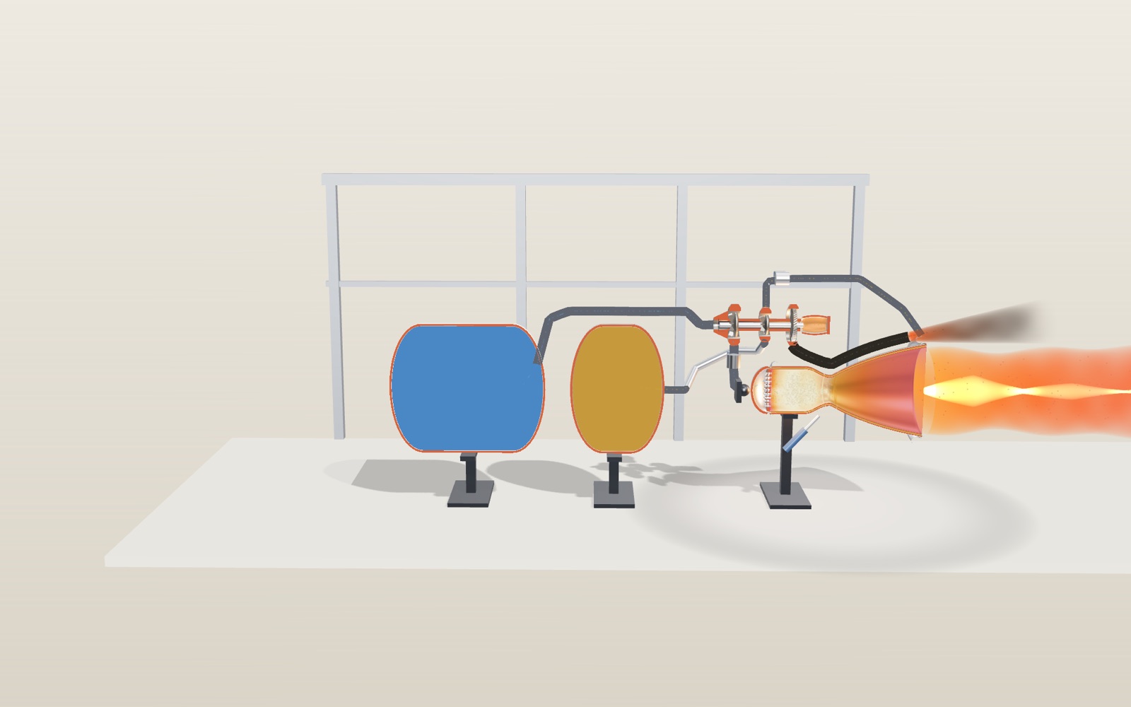
Liquid rocket engine: interactive model, how it works
Nuri's 75-tonne engine burns 255 kg of kerosene and liquid oxygen every second, and the same engine pushes about 13 percent harder in space than at sea level.
Turbocharger: interactive model, take it apart
On this model 2.0-litre engine, a shaft spinning at 142,000 rpm squeezes almost twice as much air into each cylinder.
Roller coaster physics: how roller coasters work
A train that creeps over a 42 m lift hill at 3 m/s is doing 99 km/h at the bottom, and nothing but gravity has pushed it.
How does a differential work in a car? A 3D gear model
Round a 10 m bend at 50 km/h and the outer rear wheel turns 17% faster than the inner one, yet both are driven from the same shaft.

How a QR code is read
Cover 30 % of a QR code with your hand and a phone still reads it. Cover one corner and it does not.
How a 3D printer works, layer by layer
A 20 mm cube printed in 0.2 mm layers is exactly 100 layers, each drawn by a nozzle 0.4 mm wide.
Walk down the Grand Canyon rock layers
Walk 1,360 m down the Bright Angel Trail through 13 rock layers, from a 270-million-year-old sea floor on the rim to 1.75-billion-year-old schist by the river.
How lightning and thunder work
A lightning channel heats the air to about five times the temperature of the Sun’s surface, and its thunder needs about 3 seconds to cover each kilometre to you.
Travelling at the speed of light
Light goes round the equator 7.5 times in a second, yet the same light needs 2.5 million years to reach the Andromeda galaxy.
Walk through Machu Picchu
Most of the work that holds Machu Picchu on its ridge, 60 per cent by one estimate, lies under the ground in foundations and drains nobody sees.